Teensy++ 2.0
Teensy 2.0 ++ Powering
Powering option 1 (voltage regulator, Teensy powered by USB)
Install the 3.3V voltage regulator available at pjrc.com! 5V trace has to be cut and 3V pads have to be shorted! Please refer to https://www.pjrc.com/teensy/3volt.html
DON'T CONNECT THE VCC SOLDER PADS TO ANYTHING!
Powering option 2 (external power, Teensy powered by console)
Connect Teensy's VCC solder pad to PS3's 3.3V supply (see connection diagram). 5V trace has to be cut and 3V pads have to be shorted! Please refer to https://www.pjrc.com/teensy/3volt.html
DON'T INSTALL VOLTAGE REGULATOR!
Teensy 2.0 ++ Downloads
NORway
Used to analyze dumps and also contains hex files to program the Teensy itself.
Mac OS-X patch
if you are on Mac OS-X and having problems with timeouts:
<MikeM64> hahaha, it's a dirty fix, but it seems to work XD
<MikeM64> lemme compile diffs, I got perfect writes happening on my mac now
<MikeM64> 10 writes and 2 timeouts; not bad. better than 20 timeouts / write
<MikeM64> http://pastie.org/8570558 if anyone needs it
NANDway
Project home:
- https://github.com/hjudges/NORway (previously https://github.com/Effleurage/NORway-and-NANDway but now merged in main git)
precompiled by judges : http://www.mediafire.com/?i5y1mhhh5lz62xu
Teensy NAND Pinout
Notes:
- WP: When the NANDs are mounted on the PS3 motherboard - the WP controllines are already connected to +3.3V. If Teensy is used for NANDs on the PS3 motherboard - the WP wire for each NAND can be discarded.
- Vcc: Teensy 3.3V regulator cannot power the NANDs on the PS3. The drain of the motherboard summed by the other peripherals draw too much current (~1.8A). The NANDs can be powered from external 3.3V power supply like ATX power supply (the orange 3.3V line of the ATX main connector).
NANDway usage
NANDWay.py Serial-Port 0/1 Command

  Serial-Port  Name of serial port to open (eg. COM1, COM2, /dev/ttyACM0, etc)
  0/1  NAND id number: 0-NAND0, 1-NAND1
  Commands:
  *  dump Filename [Offset] [Length]
     dumps to Filename at [Offset] and [Length]
  *  vwrite/write Filename [Offset] [Length]
     Flashes (v=verify) Filename at [Offset] and [Length]
  *  vdiffwrite/diffwrite  Filename Diff-file
     Flashes (v=verify) Filename using a Diff-file
  *  release
     Releases TRISTATE, so that the PS3 can boot
  *  bootloader
     Enters Teensy's bootloader mode (for Teensy reprogramming)
     Notes: 1) All offsets and lengths are in hex
            2) The Diff-file is a file which lists all the changed
               offsets of a dump file. This should increase flashing
               time dramatically.

Examples:

  NANDWay.py COM1
  NANDWay.py COM1 0 dump d:\myflash.bin
  NANDWay.py COM1 1 dump d:\myflash.bin 3D a0
  NANDWay.py COM1 0 write d:\myflash.bin
  NANDWay.py COM3 1 write d:\myflash.bin
  NANDWay.py COM3 1 vwrite d:\myflash.bin 8D A0000
  NANDWay.py COM4 0 diffwrite d:\myflash.bin d:\myflash_diff
  NANDWay.py COM3 1 vdiffwrite d:\myflash.bin d:\myflash_diff
  NANDWay.py COM1 0 release
NORway usage
Usage: %s serialport [command] [filename] [address]

serialport  Name of serial port to open (eg. COM1, COM2, /dev/ttyACM0, etc)
command     dump       Reads entire NOR to [filename]
            erase      Erases one sector (128KB) at [address]
            write      Flashes (read-erase-modify-write-verify) [filename]
                       at [address] to NOR
            writeimg   Same as write, but prepend a 16-byte length header
                       [address] is required
            program    Flashes (erase-write-verify) [filename]
                       at [address] to NOR
            release    Releases NOR interface, so the PS3 can boot
filename    Filename for [dump|write|writeimg|program]
address     Address for [erase|write|writeimg|program]
            Default is 0x0, address must be aligned (multiple of 0x20000)
Drivers & UDEV Rules
The Teensy 2.0++ needs windows drivers and linux udev rules to be recognized fully as it was meant to.
WAY-launchers
Simple GUI to run NORway, NANDway and SPIway.
Project home:
Hardware Picture

Installation Requirements
You are going to need a lot parts to accomplish such a task. This takes a lot of patience, and steady hands.
This is a difficult installation! If a part is not needed below it will be specified per model so check there as well.
Parts
The following items are required to perform the installation of the Teensy++ to most PS3 consoles.
1x Sony Playstation 3 Console
1x Teensy 2.0 ++
1x Dremel Tool (Not needed on some models)
1x Drill
1x Roll of Double Sided Foam Tape
1x 30AWG Kynar Wire or 26 AWG Kynar Wire. (Few have reported 30AWG may be too small and has interference but does work if done well.)
1x Torque 10(T-10) Screwdriver
1x Torque 8 (T-8) Screwdriver
1x Regular Phillips Head Screwdriver
1x Solder (Can be leaded or no-lead)
1x Soldering Iron (Radioshack 15-30 Watt Will Work.)
1x Bottle Of Flux No-Clean
1x Bottle Of 99% Isoprobyl Alcohol
1x Box of Q-Tips (For spreading flux and alcohol where needed.)
1x Pair Of Steady Hands (Not Joking. Tremor Fingers will not cut it. You are soldering 40+ points and all must be done very well.)
1x Good Lighting (Either very well lighted room, or a Lamp. You need to be able to check your work.)
1x Magnifying Glass (To check your soldering joints for cold solders.)
1x Patience.
As you can see it requires a lot of materials to perform this kind of job. If you do not already have the parts for this kind of project, it will probably be cheaper to pay someone else to do it and ship it to and from them. Also if you are not confident in your soldering technique, it is a very realistic possibility that you will ruin your Playstation 3 Console during this process as there are a LOT of soldering joints that need to be perfectly made.
Teensy Install Notes by CECH Model
First open the PS3. Follow youtube videos to learn how (Just search).
Once opened, look at the motherboard model printed there. Depending on which model you have follow the case modifications below to install teensy.
There are two methods to use a Teensy 2.0++ Flasher.
1.) Install while the PS3 is somewhat opened still with everything plugged in. (Be careful of shorts.)
2.) Internal Case Modifications. This is the best way to go as you can install the teensy inside of the PS3 for later use. This is the advantage of using a Teensy 2.0++ because it's just small enough to install inside the PS3 with a little case modification. Other flashers are generally too large to do this with the PS3 closed up. You will find there is just no room for it.
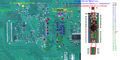
COK-001, COK-002, COK-002W, SEM-001
I used the image for the Progskeet, along with an image of which Progskeet pin(GP1 etc.) corresponds to which NAND chip pin name (WP, ALE, CLE, I/O1 etc.) to create a diagram of which testpoint on the mainboard goes to which leg of the NAND chips made by Samsung.
Diagram for wiring Teensy++ 2.0 to a PS3 COK-002 mainboard
So now you can use this diagram not only for downgrading/dumping/writing the NANDs with a Teensy++ 2.0 board, but with any other board available on the Internet.
Important: You must provide a stable 3.3V PSU to both the PS3 board and the Teensy, and don’t forget to unite the GNDs. You can use any PSU which outputs 3.3V @ 1.8A+, the easiest option will be to use a PC PSU.
DIA-001, DIA-002
Parts not needed? Submitter please list here.
Installation and Case Modification
This installation the case was not modified. It was flashed while opened, and removed.


VER-001
Usage :
1 - Connect first SB VCC 2v Max
2 - Connect in second step Vcc Teensy2++ 3.3v
Schematic for VER-001 - Teensy 2++ with External Power Only

Installation and case modification
In this installation, the cables were strategically soldered to fit better and not break or short when the power supply was placed, so no external power was needed.


DYN-001
Parts not needed - Torque T-10 Screwdriver. (T-8 IS still needed!)
Installation and Case Modifications
Be sure to make a screw map when disassembling the PS3, there are a lot of screws, and you will not remember where they go.
First and Second dremel area. These 4 pictures show before and after affects and where to dremel on the top side shielding.


Third dremel area. These pictures show before and after affects and where to dremel on the bottom side shielding.
This helps with interference by running wires outside the shielding instead of inside. This method has to be done
on these models as unlike JSD-001 Models there are no holes or spaces between the HDD and shielding. It's connected
on DYN-001 Models.
NOTE: When placing teensy, DO NOT PLACE directly on the shielding. Make sure you use a strip of double sided foam tape. to act between the shielding and teensy.


Forth and last dremel area. This is done on the case itself. The port for the teensy is covered by the HDD cover area. You will have to take care in cutting open the area. If you did not spread your wires out evenly on the underside of the shielding, it will create a raised section and the port itself will be too high to reach and may have to dremel higher.


Notes on Reassembly: Before putting back the blu-ray drive, carefully bend each wire on the topside flat by hand ONE AT A TIME so you do not break the solder joints on the teensy. If you do not bend them flat by hand one at a time carefully, the drive could easily undo one of your soldering joints and you will have to start again. (I managed to do it on the first try. Did I say that you needed 1x of Patience?
Testing: You can test your work before putting the cover top back on. Just make sure blu-ray and power-supply are connected and everything else before trying. This is so you know that everything is fitting okay and that the install has worked for you. Take 3 dumps (Read above on how to take a dump of NOR) and compare them. Do md5sum and sha1sum, and then try and unpack them with norunpack from f0f tools. If they all match, and it unpackages, congratulations you have a good dump!
JSD-001
No dremel required. Design of this CECH 2500 series has an opened hole area to put wires through.
Installation and Case Modification
File:JSD-001 testpoints.png JSD-001 Motherboard NOR Test Points. |


SUR-001/JTP-001/KTE-001
- Need submissions...
| ||||||||||||||||||||||||||||||||||||||