Talk:DualShock 4
Talk
infos merged from:
Frank's Eleccelerator
Hi, this is Frank, Eleccelerator is my website. I noticed the little message you've sent me (please use email next time, I don't check my own wiki edits, but I can't find your email either lol so I'm a hypocrite right now). Feel free to copy whatever information you want, I want the information to be public. Including a link to my website would be nice though.
Source: http://eleccelerator.com/wiki/index.php?title=DualShock_4 (full paste 17:50 UTC, 18 January 2014 )
Johndrinkwater's git
- I’ve been decoding the USB reports independently and appear to have got further along, when I’m happy that most of the packet is described, I’ll integrate my findings, still a few nibbles unaccounted for though… https://gist.github.com/johndrinkwater/7708901 -- Johndrinkwater (talk) 05:22, 3 December 2013 (EST)
See also http://blog.binaryninjas.org/?p=149
Review:
It feels really good to hold.
Hardware
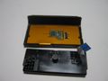
Teardown photo album: http://imgur.com/a/ytRW5
The USB port and LED are on one separate board, connected using a flat flexible cable, this cable is connected to a vertical FFC connector that does not have a locking mechanism.
Main microcontroller: is a Spansion MB9BF002, a ARM Cortex M3 core, Ball Grid Array (BGA) package. The reset and SWD signals might be exposed to test points, I am not sure.
Power Management IC (PMIC): There's a ROHM chip marked with "BD9200" (in QFN 32 pin footprint), it has some thick traces around it, plus a big inductor. One of the pins near it read 6V, might be for the motor.
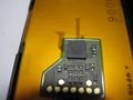
Bluetooth module: shows "8LA18366" and "GS-WCM-01" and "VR2.0". There is also a QR code that I can't decipher yet. There are a lot of test points near it. Underneath, it is confirmed to be a Qualcomm Atheros AR3002-BL3D.
Six-axis sensor: There's a rectangular, maybe Land grid array (LGA) chip on the bottom side on the left, marked with "134" "A1322" "333": Bosch-sensortec GMBH BMI055 inertial sensor used for the three-axis gyroscope and three-axis accelerometer. It's got some sort of latch signal around it, or maybe it's a weird clock. It's slow and doesn't seem like a bus. Or it could be a shift register and it's reading blank because I'm not pressing buttons.
Touchpad sensor: (with Atmel 8-bit AVR Microcontroller ATiny2313) is also detachable, connected using a flat flexible cable, this cable is connected to the main PCB using a connector that has a flip-up locking mechanism.
Speaker: (EAS1S181F) is a built-in Piezoelectric speaker connected to the main PCB using some raised contacts.
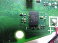
Audio codecs: There's a QFN 32 pin chip marked with "WM1801G" (Wolfson Microelectronics) "36A0LM6" dead center on the bottom side of the PCB. It is near the audio stuff but it is also near where all the buttons connect. There are 5 test points near it. It appears to be communicating with SPI BUS with constant activity. There's also two resistors that look like I²C pull-up resistors, and there appears to be constant I2C traffic.
There's a shiny small square chip left of the left analog stick, it is marked with "7710" "325A1", I have no idea what this is, but there's some differential signals coming out of it, it might be USB, the activity stops when I disconnect the USB cable. I think this is connected to the USB port. I suspect this is a OTG chip.
Some buttons are active low, some are active high (maybe only the thumbstick push buttons). The sheet of flexible circuit for the buttons are active low.
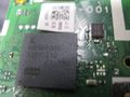
Main Micro-controller
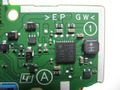
Power Management
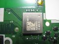
Bluetooth Module and on the left, the numbering for the flexible film.
6-axis
TouchPad
TouchPad
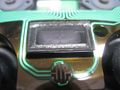
LoudSpeaker
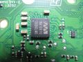
Audio Codecs


Flexible Film Pin Mapping
The buttons are all on a single sheet of flexible film. The contacts for the flexible film are numbered from 1 to 18, and the numbers are written on the PCB.
The triggers have a resistor printed directly on the film, this appears to form a Voltage divider voltage divider, so that the trigger can have an analog value. The ground side of the voltage divider appears to be oscillating, the frequency and duty cycle are not fixed or predictable.
See main page (skewed button connector) for pins purpose.