CSW-001: Difference between revisions
Jump to navigation
Jump to search
m (trying to standarize switch board pages sections) |
mNo edit summary |
||
| Line 9: | Line 9: | ||
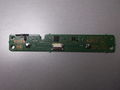
File:Power Eject board CSW-001 (PCB bottom view).jpg|Switch board CSW-001 (PCB bottom view) | File:Power Eject board CSW-001 (PCB bottom view).jpg|Switch board CSW-001 (PCB bottom view) | ||
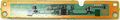
File:Vyr_20DSCF0178.jpg|CSW-001 1-871-871-11 | File:Vyr_20DSCF0178.jpg|CSW-001 1-871-871-11 | ||
File:Flat Flex Ribbon Cable 10pins.png|Flat Flex Ribbon Cable 10pins (fixed by the ghetto way) | |||
</gallery> | </gallery> | ||
| Line 14: | Line 15: | ||
{{CSW-001 pinout}} | {{CSW-001 pinout}} | ||
*Eject LED should be connected to BD controller [[CXD5063AGG-1]] | *Eject LED should be connected to BD controller [[CXD5063AGG-1]] | ||
*Other signal pins should be connected to | *Other signal pins should be connected to [[Syscon CXR713 Series]] | ||
= How it works = | = How it works = | ||
Revision as of 17:53, 14 September 2018
Description
- Part number: 1-871-871-21
- CSW-001 is a switch board compatible with PS3 models:
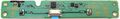
Switch board CSW-001 (PCB top view)
Switch board CSW-001 (PCB bottom view)
CSW-001 1-871-871-11
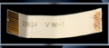
Flat Flex Ribbon Cable 10pins (fixed by the ghetto way)


Pinout
| Pin | Name | Connected to | Description | |
|---|---|---|---|---|
| On Motherboard | On Switch board | |||
| 1 | GND | GND | GND | Ground |
| 2 | SW_PWM | Syscon pad N9 | Testpad ? | FREQ. Intended to send a PWM signal to the switch board ? |
| 3 | RMC_IN | Syscon pad R10 Service Connector (CN4009) pin 17 |
Testpad ?. NC | ReMote Control INput The IR receiver component is missing in the Switch board but existed in some PS3 prototypes that was using SIRC protocol and SERV_SIRCS |
| 4 | POW_SW | Syscon pad B12 | Power Switch |
|
| 5 | EJECT_SW | Syscon pad A12 | Eject Switch |
|
| 6 | POW_LED | Syscon pad M7 | Green led | |
| 7 | STBY_LED | Syscon pad N7 | Red led | |
| 8 | BD_LED | BluRay connector (CN3221) pin 50 | Blue led | |
| 9 | GND | GND | GND | Ground |
| 10 | +5V_EVER | Power Supply connector (CN6005) pins 4 and 5 | VCC | 5V Standby |
- Eject LED should be connected to BD controller CXD5063AGG-1
- Other signal pins should be connected to Syscon CXR713 Series
How it works
Modding
| ||||||||||||||||||||||||||||||||||||||||||||||||||||||||||||||||||||||||||||||||||||||||||||||||||||||||||||||||||||||||||||||||||||
