KLMAG2GE4A-A001: Difference between revisions
Jump to navigation
Jump to search
m (yup, those are there) |
|||
| Line 15: | Line 15: | ||
=== Testpoints eMMC === | === Testpoints eMMC === | ||
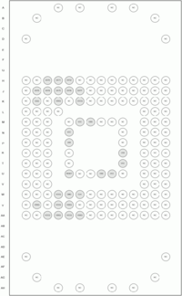
<div style="float:right">[[File:EMMC-BGA169.png|200px|thumb|left|eMMC-BGA169]]</div> | |||
<div style="height:550px; overflow:auto"> | <div style="height:550px; overflow:auto"> | ||
{| border="1" cellspacing="0" cellpadding="5" border="#999" class="wikitable" style="border:1px solid #999; border-collapse: collapse;" | {| border="1" cellspacing="0" cellpadding="5" border="#999" class="wikitable" style="border:1px solid #999; border-collapse: collapse;" | ||
|- | |- | ||
! eMMC<br />Testpoint !! Pad # !! Name !! Description | ! eMMC<br />Testpoint !! Pad # !! Name !! Type !! Description | ||
|- | |- | ||
| - || A-G 1-14 || NP or NC || not | | - || A-G 1-14 || - || NP or NC || not present or not connected | ||
|- | |- | ||
| || H3 || DAT0 || | | || H3 || DAT0 || I/O || Data I/O : Bidirectional channel used for data transfer | ||
|- | |- | ||
| || H4 || DAT1 || | | || H4 || DAT1 || I/O || Data I/O : Bidirectional channel used for data transfer | ||
|- | |- | ||
| || H5 || DAT2 || | | || H5 || DAT2 || I/O || Data I/O : Bidirectional channel used for data transfer | ||
|- | |- | ||
| || J2 || DAT3 || | | || J2 || DAT3 || I/O || Data I/O : Bidirectional channel used for data transfer | ||
|- | |- | ||
| || J3 || DAT4 || | | || J3 || DAT4 || I/O || Data I/O : Bidirectional channel used for data transfer | ||
|- | |- | ||
| || J4 || DAT5 || | | || J4 || DAT5 || I/O || Data I/O : Bidirectional channel used for data transfer | ||
|- | |- | ||
| || J5 || DAT6 || | | || J5 || DAT6 || I/O || Data I/O : Bidirectional channel used for data transfer | ||
|- | |- | ||
| || J6 || DAT7 || | | || J6 || DAT7 || I/O || Data I/O : Bidirectional channel used for data transfer | ||
|- | |- | ||
| || K2 || VDDi || | | || K2 || VDDi || || Internal power node. Connect 0.1uF capacitor from VDDi to ground. | ||
|- | |- | ||
| || K4 || VSSQ || | | || K4 || VSSQ || Ground || Memory controller core and MMC IF ground connection | ||
|- | |- | ||
| || K6 || VSSQ || | | || K6 || VSSQ || Supply || Memory controller core and MMC IF I/O power supply | ||
|- | |- | ||
| || M6 || VCC || | | || M6 || VCC || Supply || Flash I/O and memory power supply | ||
|- | |- | ||
| || M7 || VSS || | | || M7 || VSS || Ground || Flash I/O and memory ground connection | ||
|- | |- | ||
| || N5 || VCC || | | || N5 || VCC || Supply || Flash I/O and memory power supply | ||
|- | |- | ||
| || P5 || VSS || | | || P5 || VSS || Ground || Flash I/O and memory ground connection | ||
|- | |- | ||
| || R10 || VSS || | | || R10 || VSS || Ground || Flash I/O and memory ground connection | ||
|- | |- | ||
| || T10 || VCC || | | || T10 || VCC || Supply || Flash I/O and memory power supply | ||
|- | |- | ||
| || U5 || RESET || | | || U5 || RESET || Hardware Reset | ||
|- | |- | ||
| || U8 || VSS || | | || U8 || VSS || Ground || Flash I/O and memory ground connection | ||
|- | |- | ||
| || U9 || VCC || | | || U9 || VCC || Supply || Flash I/O and memory power supply | ||
|- | |- | ||
| || W4 || VCCQ || | | || W4 || VCCQ || Supply || Memory controller core and MMC IF I/O power supply | ||
|- | |- | ||
| || W5 || CMD || | | || W5 || CMD || I/O || Command: A bidirectional channel used for device initialisation and command transfers | ||
|- | |- | ||
| || W6 || CLK || | | || W6 || CLK || Input || Clock: Each cycle directs a 1-bit transfer on the command and DAT lines | ||
|- | |- | ||
| || Y2 || VSSQ || | | || Y2 || VSSQ || Ground || Memory controller core and MMC IF ground connection | ||
|- | |- | ||
| || Y4 || VCCQ || | | || Y4 || VCCQ || Supply || Memory controller core and MMC IF I/O power supply | ||
|- | |- | ||
| || Y5 || VSSQ || | | || Y5 || VSSQ || Ground || Memory controller core and MMC IF ground connection | ||
|- | |- | ||
| || AA3 || VCCQ || | | || AA3 || VCCQ || Supply || Memory controller core and MMC IF I/O power supply | ||
|- | |- | ||
| || AA4 || VSSQ || | | || AA4 || VSSQ || Ground || Memory controller core and MMC IF ground connection | ||
|- | |- | ||
| || AA5 || VCCQ || | | || AA5 || VCCQ || Supply || Memory controller core and MMC IF I/O power supply | ||
|- | |- | ||
| || AA6 || VSSQ || | | || AA6 || VSSQ || Ground || Memory controller core and MMC IF ground connection | ||
|- | |- | ||
| || AB-HG 1-14 || NP or NC || not | | || AB-HG 1-14 || - || NP or NC || not present or not connected | ||
|- | |- | ||
|} | |} | ||
''remark: the following Pad #letter's are not used: I, O, Q, S, X, Z, AI, AO, AQ, AS, AX, AZ'' | ''remark: the following Pad #letter's are not used: I, O, Q, S, X, Z, AI, AO, AQ, AS, AX, AZ'' | ||
</div> | </div> | ||
Revision as of 03:23, 14 February 2013
| This article is a stub. You can help PS3 Developer wiki by expanding it. |
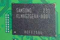
Samsung KLMAG2GE4A-A001
Used in 'Super Slim 12GB' CECH-4003A MPX-001 accompanied by Panasonic MN66840
eMMC MLC NAND
FBGA169
[Embedded MMC (eMMC) Standard MMCA 4.4 (JESD84-A44)(March 2009)]
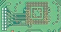
Testpoints eMMC
| eMMC Testpoint |
Pad # | Name | Type | Description |
|---|---|---|---|---|
| - | A-G 1-14 | - | NP or NC | not present or not connected |
| H3 | DAT0 | I/O | Data I/O : Bidirectional channel used for data transfer | |
| H4 | DAT1 | I/O | Data I/O : Bidirectional channel used for data transfer | |
| H5 | DAT2 | I/O | Data I/O : Bidirectional channel used for data transfer | |
| J2 | DAT3 | I/O | Data I/O : Bidirectional channel used for data transfer | |
| J3 | DAT4 | I/O | Data I/O : Bidirectional channel used for data transfer | |
| J4 | DAT5 | I/O | Data I/O : Bidirectional channel used for data transfer | |
| J5 | DAT6 | I/O | Data I/O : Bidirectional channel used for data transfer | |
| J6 | DAT7 | I/O | Data I/O : Bidirectional channel used for data transfer | |
| K2 | VDDi | Internal power node. Connect 0.1uF capacitor from VDDi to ground. | ||
| K4 | VSSQ | Ground | Memory controller core and MMC IF ground connection | |
| K6 | VSSQ | Supply | Memory controller core and MMC IF I/O power supply | |
| M6 | VCC | Supply | Flash I/O and memory power supply | |
| M7 | VSS | Ground | Flash I/O and memory ground connection | |
| N5 | VCC | Supply | Flash I/O and memory power supply | |
| P5 | VSS | Ground | Flash I/O and memory ground connection | |
| R10 | VSS | Ground | Flash I/O and memory ground connection | |
| T10 | VCC | Supply | Flash I/O and memory power supply | |
| U5 | RESET | Hardware Reset | ||
| U8 | VSS | Ground | Flash I/O and memory ground connection | |
| U9 | VCC | Supply | Flash I/O and memory power supply | |
| W4 | VCCQ | Supply | Memory controller core and MMC IF I/O power supply | |
| W5 | CMD | I/O | Command: A bidirectional channel used for device initialisation and command transfers | |
| W6 | CLK | Input | Clock: Each cycle directs a 1-bit transfer on the command and DAT lines | |
| Y2 | VSSQ | Ground | Memory controller core and MMC IF ground connection | |
| Y4 | VCCQ | Supply | Memory controller core and MMC IF I/O power supply | |
| Y5 | VSSQ | Ground | Memory controller core and MMC IF ground connection | |
| AA3 | VCCQ | Supply | Memory controller core and MMC IF I/O power supply | |
| AA4 | VSSQ | Ground | Memory controller core and MMC IF ground connection | |
| AA5 | VCCQ | Supply | Memory controller core and MMC IF I/O power supply | |
| AA6 | VSSQ | Ground | Memory controller core and MMC IF ground connection | |
| AB-HG 1-14 | - | NP or NC | not present or not connected |
remark: the following Pad #letter's are not used: I, O, Q, S, X, Z, AI, AO, AQ, AS, AX, AZ


