KLMAG2GE4A-A001: Difference between revisions
Jump to navigation
Jump to search
mNo edit summary |
(Greengrocers comma removal) |
||
| (27 intermediate revisions by 3 users not shown) | |||
| Line 1: | Line 1: | ||
== Samsung [[KLMAG2GE4A-A001]] == | == Samsung [[KLMAG2GE4A-A001]] == | ||
<div style="float:right">[[File:Samsung KLMAG2GE4A-A001.jpg|200px|thumb|left|Samsung KLMAG2GE4A-A001]]<br />[[File:Superslim missing component close to SB.jpg|200px|thumb|left|Pads when no eMMC present]]</div> | <div style="float:right">[[File:Samsung KLMAG2GE4A-A001.jpg|200px|thumb|left|Samsung KLMAG2GE4A-A001]]<br />[[File:Superslim missing component close to SB.jpg|200px|thumb|left|Pads when no eMMC present]]</div> | ||
Used in 'Super Slim 12GB' [[CECH-40xx|CECH-4003A]] [[MPX-00x|MPX-001]] accompanied by Panasonic [[MN66840]]<br /> | Used in 'Super Slim 12GB' [[CECH-40xx|CECH-4003A]] [[MPX-00x|MPX-001]] accompanied by Panasonic [[MN66840]]<br /> | ||
Partnumber: KLMAG2GE4A-A00x | Partnumber: KLMAG2GE4A-A00x | ||
| Line 14: | Line 13: | ||
Organisation: x8 | Organisation: x8 | ||
Voltage : 1.7 - 1.95V / 2.7 - 3.6V | Voltage : 1.7 - 1.95V / 2.7 - 3.6V | ||
variants: | |||
* in [http://wiiubrew.org/wiki/EMMC_NAND Wii-U consoles]: Samsung KLM8G2FE3B-B001 (8GB class100 BGA153) or KLMBG4GE4A-A001 (32GB class400 BGA169) | |||
* in [http://desmond.imageshack.us/Himg96/scaled.php?server=96&filename=img0889kf.jpg&res=landing Xbox 360 consoles]: Samsung KLM4G1HE3F-B001 (4GB class50 BGA153) | |||
* in [http://www.techinsights.com/teardowns/sony-playstation-vita-teardown/ PSVita PCH-1000]: Toshiba [http://download.siliconexpert.com/pdfs/2010/12/11/22/49/47/571/tos_/manual/thgbm3g5d1fbaie32nm4gbe-mmc_e_rev0.3_100917.pdf THGBM3G5D1FBAIE] | |||
* in [http://www.4gamer.net/games/990/G999021/20131013001/ PSVita PCH-2000]: Toshiba THGBMAG5A1JBAIR | |||
* in other PSVita PCH-2000: Sandisk {{unk|?}} | |||
* in [http://www.ifixit.com/Teardown/PlayStation+Vita+Teardown/7872 other PSVita] [http://yifan.lu/2013/12/18/removing-the-cpu-and-nand-from-psvita/#more-670 PCH-1000] and [http://www.4gamer.net/games/990/G999021/20131115043/ VitaTV]: Samsung KLM4G1FE3A-F001 | |||
* in [http://www.konsolen-junkies.de/images/one_nand1.jpg Xbox-one]: SK Hynix H26M42003GMR 8GB eMMC NAND Flash | |||
* in [http://3dbrew.org/wiki/Hardware#NAND_pinout 3DS]: Toshiba THGBM2G3P1FBAI8 1GB eMMC NAND flash | |||
http://www.samsung.com/global/business/semiconductor/product/flash-emmc/overview | http://www.samsung.com/global/business/semiconductor/product/flash-emmc/overview | ||
Handy PDFs | === Handy PDFs === | ||
* [http://www.jedec.org/sites/default/files/docs/JESD84-A44.pdf Embedded MMC (eMMC) Standard MMCA 4.4 (JESD84-A44)(March 2009)]<br /> | * [http://www.jedec.org/sites/default/files/docs/JESD84-A44.pdf Embedded MMC (eMMC) Standard MMCA 4.4 (JESD84-A44)(March 2009)]<br /> | ||
* [http://omapworld.com/iNAND_e_MMC_4_41_IF_data_sheet_v1_0%5B1%5D.pdf iNAND_e_MMC_4_41_IF_data_sheet_v1_0.pdf] | * [http://omapworld.com/iNAND_e_MMC_4_41_IF_data_sheet_v1_0%5B1%5D.pdf iNAND_e_MMC_4_41_IF_data_sheet_v1_0.pdf] | ||
| Line 24: | Line 33: | ||
* [http://www.freescale.com/files/training_pdf/WBNR_FTF10_NET_F0598_PDF.pdf WBNR_FTF10_NET_F0598_PDF.pdf] | * [http://www.freescale.com/files/training_pdf/WBNR_FTF10_NET_F0598_PDF.pdf WBNR_FTF10_NET_F0598_PDF.pdf] | ||
See also : http://www.vitadevwiki.com/index.php?title=Media | See also : | ||
* http://www.vitadevwiki.com/index.php?title=Media | |||
* http://en.wikipedia.org/wiki/MultiMediaCard#MMCplus_and_MMCmobile | |||
* http://en.wikipedia.org/wiki/Secure_Digital#Transfer_modes | |||
=== Testpoints eMMC === | === Testpoints eMMC === | ||
<div style="float:right">[[File:EMMC-BGA169.png|200px|thumb|left|eMMC-BGA169]]<br />[[File:EMMC - colormapping - front.jpg|200px|thumb|left| | <div style="float:right">[[File:EMMC-BGA169.png|200px|thumb|left|eMMC-BGA169]]<br />[[File:EMMC - colormapping - front.jpg|200px|thumb|left|eMMC - colormapping - front]]<br />[[File:EMMC - colormapping - back.jpg|200px|thumb|left|eMMC - colormapping - back]]<br />[[File:MMC-13pads-layout.png|200px|thumb|left|MMC-plus 13pad layout]]<br />[[File:MMC-SD-miniSD-microSD-Color-Numbers-Names.jpg|200px|thumb|left|MMC, SD, miniSD, microSD cards pinout]]<br />[[File:EMMC Wii-U.jpg|200px|thumb|left|eMMC in Wii-U - pinout]]<br />[[File:EMMC Wii-U-removed.jpg|200px|thumb|left|eMMC in Wii-U removed (as you can see, only 4-bit mode is used)]]</div> | ||
< | |||
{| border="1" cellspacing="0" cellpadding="5" border="#999" class="wikitable" style="border:1px solid #999; border-collapse: collapse;" | {| border="1" cellspacing="0" cellpadding="5" border="#999" class="wikitable sortable" style="border:1px solid #999; border-collapse: collapse;" | ||
|- | |- | ||
! Color !! eMMC<br />Testpoint !! Pad # !! Name !! Type !! Description | ! Color !! eMMC<br />Testpoint !! BGA169<br />Pad # !! MMC-plus<br />(1-,4-,8-bit)<br />Pad # !! MMC<br />(1bit)<br />Pad # !! SD<br />(1-,4-bit)<br />Pad # !! miniSD<br />(1-,4-bit)<br />Pad # !! microSD<br />(1-,4-bit)<br />Pad # !! Name !! Type !! Description | ||
|- | |- | ||
| - || A-G 1-14 || - || NP or NC || not present or not connected | | - || - || A-G 1-14 || - || - || - || - || - || NP or NC || - || not present or not connected | ||
|- | |- | ||
| style="color:white; background-color:#B0B0FF;" | || B4 || H3 || | | style="color:white; background-color:#B0B0FF;" | || B4 || H3 || 07 || 07 || 07 || 07 || 07 || DATA0 || I/O || Data I/O : Bidirectional channel used for data transfer | ||
|- | |- | ||
| style="color:white; background-color:#B0B0FF;" | || B5 || H4 || | | style="color:white; background-color:#B0B0FF;" | || B5 || H4 || 08 || - || 08 || 08 || 08 || DATA1 || I/O || Data I/O : Bidirectional channel used for data transfer | ||
|- | |- | ||
| style="color:white; background-color:#B0B0FF;" | || B6 || H5 || | | style="color:white; background-color:#B0B0FF;" | || B6 || H5 || 09 || - || 09 || 09 || 01 || DATA2 || I/O || Data I/O : Bidirectional channel used for data transfer | ||
|- | |- | ||
| style="color:white; background-color:#B0B0FF;" | || B2 || J2 || | | style="color:white; background-color:#B0B0FF;" | || B2 || J2 || 01 || 01 (NC) || 01 || 01 || 02 || DATA3 || I/O || Data I/O : Bidirectional channel used for data transfer | ||
|- | |- | ||
| style="color:white; background-color:#B0B0FF;" | || B3 || J3 || | | style="color:white; background-color:#B0B0FF;" | || B3 || J3 || 10 || - || - || - || - || DATA4 || I/O || Data I/O : Bidirectional channel used for data transfer | ||
|- | |- | ||
| style="color:white; background-color:#B0B0FF;" | || B1 || J4 || | | style="color:white; background-color:#B0B0FF;" | || B1 || J4 || 11 || - || - || - || - || DATA5 || I/O || Data I/O : Bidirectional channel used for data transfer | ||
|- | |- | ||
| style="color:white; background-color:#B0B0FF;" | || B7 || J5 || | | style="color:white; background-color:#B0B0FF;" | || B7 || J5 || 12 || - || - || - || - || DATA6 || I/O || Data I/O : Bidirectional channel used for data transfer | ||
|- | |- | ||
| style="color:white; background-color:#B0B0FF;" | || B8 || J6 || | | style="color:white; background-color:#B0B0FF;" | || B8 || J6 || 13 || - || - || - || - || DATA7 || I/O || Data I/O : Bidirectional channel used for data transfer | ||
|- | |- | ||
| style="color:white; background-color:#FFA4A4;" | || || K2 || VDDi || | | style="color:white; background-color:#FFA4A4;" | || || K2 || 04 || 04 || 04 || 04 || 04 || VDDi || Supply || Internal power node. Connect 0.1uF capacitor from VDDi to ground. | ||
|- | |- | ||
| style="color:white; background-color:#C0C0C0;" | || || K4 || VSSQ || Ground || Memory controller core and MMC IF ground connection | | style="color:white; background-color:#C0C0C0;" | || || K4 || 03 / 06 || 03 / 06 || 03 / 06 || 03 / 06 || 06 || VSSQ || Ground || Memory controller core and MMC IF ground connection | ||
|- | |- | ||
| style="color:white; background-color:#FF8000;" | || || K6 || VCCQ || Supply || Memory controller core and MMC IF I/O power supply | | style="color:white; background-color:#FF8000;" | || || K6 || 04 || 04 || 04 || 04 || 04 || VCCQ || Supply || Memory controller core and MMC IF I/O power supply | ||
|- | |- | ||
| style="color:white; background-color:#FF0000;" | || || M6 || VCC || Supply || Flash I/O and memory power supply | | style="color:white; background-color:#FF0000;" | || || M6 || 04 || 04 || 04 || 04 || 04 || VCC || Supply || Flash I/O and memory power supply | ||
|- | |- | ||
| style="color:white; background-color:#C0C0C0;" | || || M7 || VSS || Ground || Flash I/O and memory ground connection | | style="color:white; background-color:#C0C0C0;" | || || M7 || 03 / 06 || 03 / 06 || 03 / 06 || 03 / 06 || 06 || VSS || Ground || Flash I/O and memory ground connection | ||
|- | |- | ||
| style="color:white; background-color:#FF0000;" | || || N5 || VCC || Supply || Flash I/O and memory power supply | | style="color:white; background-color:#FF0000;" | || || N5 || 04 || 04 || 04 || 04 || 04 || VCC || Supply || Flash I/O and memory power supply | ||
|- | |- | ||
| style="color:white; background-color:#C0C0C0;" | || || P5 || VSS || Ground || Flash I/O and memory ground connection | | style="color:white; background-color:#C0C0C0;" | || || P5 || 03 / 06 || 03 / 06 || 03 / 06 || 03 / 06 || 06 || VSS || Ground || Flash I/O and memory ground connection | ||
|- | |- | ||
| style="color:white; background-color:#C0C0C0;" | || || R10 || VSS || Ground || Flash I/O and memory ground connection | | style="color:white; background-color:#C0C0C0;" | || || R10 || 03 / 06 || 03 / 06 || 03 / 06 || 03 / 06 || 06 || VSS || Ground || Flash I/O and memory ground connection | ||
|- | |- | ||
| style="color:white; background-color:#FF0000;" | || || T10 || VCC || Supply || Flash I/O and memory power supply | | style="color:white; background-color:#FF0000;" | || || T10 || 04 || 04 || 04 || 04 || 04 || VCC || Supply || Flash I/O and memory power supply | ||
|- | |- | ||
| - || U5 || RESET || Hardware Reset | | - || - || U5 || - || - || - || - || - || RESET || Input || Hardware Reset (not connected on PS3 and Wii-U) | ||
|- | |- | ||
| style="color:white; background-color:#C0C0C0;" | || || U8 || VSS || Ground || Flash I/O and memory ground connection | | style="color:white; background-color:#C0C0C0;" | || || U8 || 03 / 06 || 03 / 06 || 03 / 06 || 03 / 06 || 06 || VSS || Ground || Flash I/O and memory ground connection | ||
|- | |- | ||
| style="color:white; background-color:#FF0000;" | || || U9 || VCC || Supply || Flash I/O and memory power supply | | style="color:white; background-color:#FF0000;" | || || U9 || 04 || 04 || 04 || 04 || 04 || VCC || Supply || Flash I/O and memory power supply | ||
|- | |- | ||
| style="color:white; background-color:#FF8000;" | || || W4 || VCCQ || Supply || Memory controller core and MMC IF I/O power supply | | style="color:white; background-color:#FF8000;" | || || W4 || 04 || 04 || 04 || 04 || 04 || VCCQ || Supply || Memory controller core and MMC IF I/O power supply | ||
|- | |- | ||
| style="color:white; background-color:#FFFF00;" | || || W5 || CMD || I/O || Command: A bidirectional channel used for device initialisation and command transfers | | style="color:white; background-color:#FFFF00;" | || || W5 || 02 || 02 || 02 || 02 || 03 || CMD || I/O || Command: A bidirectional channel used for device initialisation and command transfers | ||
|- | |- | ||
| style="color:white; background-color:#00FF00;" | || || W6 || CLK || Input || Clock: Each cycle directs a 1-bit transfer on the command and DAT lines | | style="color:white; background-color:#00FF00;" | || || W6 || 05 || 05 || 05 || 05 || 05 || CLK || Input || Clock: Each cycle directs a 1-bit transfer on the command and DAT lines | ||
|- | |- | ||
| style="color:white; background-color:#C0C0C0;" | || || Y2 || VSSQ || Ground || Memory controller core and MMC IF ground connection | | style="color:white; background-color:#C0C0C0;" | || || Y2 || 03 / 06 || 03 / 06 || 03 / 06 || 03 / 06 || 06 || VSSQ || Ground || Memory controller core and MMC IF ground connection | ||
|- | |- | ||
| style="color:white; background-color:#FF8000;" | || || Y4 || VCCQ || Supply || Memory controller core and MMC IF I/O power supply | | style="color:white; background-color:#FF8000;" | || || Y4 || 04 || 04 || 04 || 04 || 04 || VCCQ || Supply || Memory controller core and MMC IF I/O power supply | ||
|- | |- | ||
| style="color:white; background-color:#C0C0C0;" | || || Y5 || VSSQ || Ground || Memory controller core and MMC IF ground connection | | style="color:white; background-color:#C0C0C0;" | || || Y5 || 03 / 06 || 03 / 06 || 03 / 06 || 03 / 06 || 06 || VSSQ || Ground || Memory controller core and MMC IF ground connection | ||
|- | |- | ||
| style="color:white; background-color:#FF8000;" | || || AA3 || VCCQ || Supply || Memory controller core and MMC IF I/O power supply | | style="color:white; background-color:#FF8000;" | || || AA3 || 04 || 04 || 04 || 04 || 04 || VCCQ || Supply || Memory controller core and MMC IF I/O power supply | ||
|- | |- | ||
| style="color:white; background-color:#C0C0C0;" | || || AA4 || VSSQ || Ground || Memory controller core and MMC IF ground connection | | style="color:white; background-color:#C0C0C0;" | || || AA4 || 03 / 06 || 03 / 06 || 03 / 06 || 03 / 06 || 06 || VSSQ || Ground || Memory controller core and MMC IF ground connection | ||
|- | |- | ||
| style="color:white; background-color:#FF8000;" | || || AA5 || VCCQ || Supply || Memory controller core and MMC IF I/O power supply | | style="color:white; background-color:#FF8000;" | || || AA5 || 04 || 04 || 04 || 04 || 04 || VCCQ || Supply || Memory controller core and MMC IF I/O power supply | ||
|- | |- | ||
| style="color:white; background-color:#C0C0C0;" | || || AA6 || VSSQ || Ground || Memory controller core and MMC IF ground connection | | style="color:white; background-color:#C0C0C0;" | || || AA6 || 03 / 06 || 03 / 06 || 03 / 06 || 03 / 06 || 06 || VSSQ || Ground || Memory controller core and MMC IF ground connection | ||
|- | |- | ||
| | | - || - || AB-HG 1-14 || - || - || - || - || - || NP or NC || - || not present or not connected | ||
|- | |- | ||
|} | |} | ||
''remark: the following Pad #letter's are not used: I, O, Q, S, X, Z, AI, AO, AQ, AS, AX, AZ'' | ''remark: the following Pad #letter's are not used: I, O, Q, S, X, Z, AI, AO, AQ, AS, AX, AZ'' | ||
'''Note:''' for hooking up to SD card reader the following might be needed: | |||
* 50K nominal (10K - 90K range) Ohm pullup between VCC and DAT3/CD for card detect (see also [http://www.nxp.com/documents/application_note/AN10911.pdf Application Notes 10911]) | |||
=== Connecting to reader === | |||
<GALLERY> | |||
File:Fake SDcard - example 1.jpg|Fake SDcard - example 1 | |||
File:Fake SDcard - example 2.jpg|Fake SDcard - example 2 | |||
</GALLERY> | |||
[[Category: | {{Motherboard Components}}<noinclude>[[Category:Main]]</noinclude> | ||
Revision as of 13:27, 18 June 2017
Samsung KLMAG2GE4A-A001


Used in 'Super Slim 12GB' CECH-4003A MPX-001 accompanied by Panasonic MN66840
Partnumber: KLMAG2GE4A-A00x
Density:    16GB
Controller: VHX
Package: 169-ball BGA
Package type: 2 chip (DDP)
Package size: 12mm x 16mm
MMC version: eMMC4.41
Class: Class400
Organisation: x8
Voltage : 1.7 - 1.95V / 2.7 - 3.6V
variants:
- in Wii-U consoles: Samsung KLM8G2FE3B-B001 (8GB class100 BGA153) or KLMBG4GE4A-A001 (32GB class400 BGA169)
- in Xbox 360 consoles: Samsung KLM4G1HE3F-B001 (4GB class50 BGA153)
- in PSVita PCH-1000: Toshiba THGBM3G5D1FBAIE
- in PSVita PCH-2000: Toshiba THGBMAG5A1JBAIR
- in other PSVita PCH-2000: Sandisk ???
- in other PSVita PCH-1000 and VitaTV: Samsung KLM4G1FE3A-F001
- in Xbox-one: SK Hynix H26M42003GMR 8GB eMMC NAND Flash
- in 3DS: Toshiba THGBM2G3P1FBAI8 1GB eMMC NAND flash
http://www.samsung.com/global/business/semiconductor/product/flash-emmc/overview
Handy PDFs
- Embedded MMC (eMMC) Standard MMCA 4.4 (JESD84-A44)(March 2009)
- iNAND_e_MMC_4_41_IF_data_sheet_v1_0.pdf
- JESD84-A44.pdf
- Victor_Tsai.pdf
- WBNR_FTF10_NET_F0598_PDF.pdf
See also :
- http://www.vitadevwiki.com/index.php?title=Media
- http://en.wikipedia.org/wiki/MultiMediaCard#MMCplus_and_MMCmobile
- http://en.wikipedia.org/wiki/Secure_Digital#Transfer_modes
Testpoints eMMC


| Color | eMMC Testpoint |
BGA169 Pad # |
MMC-plus (1-,4-,8-bit) Pad # |
MMC (1bit) Pad # |
SD (1-,4-bit) Pad # |
miniSD (1-,4-bit) Pad # |
microSD (1-,4-bit) Pad # |
Name | Type | Description |
|---|---|---|---|---|---|---|---|---|---|---|
| - | - | A-G 1-14 | - | - | - | - | - | NP or NC | - | not present or not connected |
| B4 | H3 | 07 | 07 | 07 | 07 | 07 | DATA0 | I/O | Data I/O : Bidirectional channel used for data transfer | |
| B5 | H4 | 08 | - | 08 | 08 | 08 | DATA1 | I/O | Data I/O : Bidirectional channel used for data transfer | |
| B6 | H5 | 09 | - | 09 | 09 | 01 | DATA2 | I/O | Data I/O : Bidirectional channel used for data transfer | |
| B2 | J2 | 01 | 01 (NC) | 01 | 01 | 02 | DATA3 | I/O | Data I/O : Bidirectional channel used for data transfer | |
| B3 | J3 | 10 | - | - | - | - | DATA4 | I/O | Data I/O : Bidirectional channel used for data transfer | |
| B1 | J4 | 11 | - | - | - | - | DATA5 | I/O | Data I/O : Bidirectional channel used for data transfer | |
| B7 | J5 | 12 | - | - | - | - | DATA6 | I/O | Data I/O : Bidirectional channel used for data transfer | |
| B8 | J6 | 13 | - | - | - | - | DATA7 | I/O | Data I/O : Bidirectional channel used for data transfer | |
| K2 | 04 | 04 | 04 | 04 | 04 | VDDi | Supply | Internal power node. Connect 0.1uF capacitor from VDDi to ground. | ||
| K4 | 03 / 06 | 03 / 06 | 03 / 06 | 03 / 06 | 06 | VSSQ | Ground | Memory controller core and MMC IF ground connection | ||
| K6 | 04 | 04 | 04 | 04 | 04 | VCCQ | Supply | Memory controller core and MMC IF I/O power supply | ||
| M6 | 04 | 04 | 04 | 04 | 04 | VCC | Supply | Flash I/O and memory power supply | ||
| M7 | 03 / 06 | 03 / 06 | 03 / 06 | 03 / 06 | 06 | VSS | Ground | Flash I/O and memory ground connection | ||
| N5 | 04 | 04 | 04 | 04 | 04 | VCC | Supply | Flash I/O and memory power supply | ||
| P5 | 03 / 06 | 03 / 06 | 03 / 06 | 03 / 06 | 06 | VSS | Ground | Flash I/O and memory ground connection | ||
| R10 | 03 / 06 | 03 / 06 | 03 / 06 | 03 / 06 | 06 | VSS | Ground | Flash I/O and memory ground connection | ||
| T10 | 04 | 04 | 04 | 04 | 04 | VCC | Supply | Flash I/O and memory power supply | ||
| - | - | U5 | - | - | - | - | - | RESET | Input | Hardware Reset (not connected on PS3 and Wii-U) |
| U8 | 03 / 06 | 03 / 06 | 03 / 06 | 03 / 06 | 06 | VSS | Ground | Flash I/O and memory ground connection | ||
| U9 | 04 | 04 | 04 | 04 | 04 | VCC | Supply | Flash I/O and memory power supply | ||
| W4 | 04 | 04 | 04 | 04 | 04 | VCCQ | Supply | Memory controller core and MMC IF I/O power supply | ||
| W5 | 02 | 02 | 02 | 02 | 03 | CMD | I/O | Command: A bidirectional channel used for device initialisation and command transfers | ||
| W6 | 05 | 05 | 05 | 05 | 05 | CLK | Input | Clock: Each cycle directs a 1-bit transfer on the command and DAT lines | ||
| Y2 | 03 / 06 | 03 / 06 | 03 / 06 | 03 / 06 | 06 | VSSQ | Ground | Memory controller core and MMC IF ground connection | ||
| Y4 | 04 | 04 | 04 | 04 | 04 | VCCQ | Supply | Memory controller core and MMC IF I/O power supply | ||
| Y5 | 03 / 06 | 03 / 06 | 03 / 06 | 03 / 06 | 06 | VSSQ | Ground | Memory controller core and MMC IF ground connection | ||
| AA3 | 04 | 04 | 04 | 04 | 04 | VCCQ | Supply | Memory controller core and MMC IF I/O power supply | ||
| AA4 | 03 / 06 | 03 / 06 | 03 / 06 | 03 / 06 | 06 | VSSQ | Ground | Memory controller core and MMC IF ground connection | ||
| AA5 | 04 | 04 | 04 | 04 | 04 | VCCQ | Supply | Memory controller core and MMC IF I/O power supply | ||
| AA6 | 03 / 06 | 03 / 06 | 03 / 06 | 03 / 06 | 06 | VSSQ | Ground | Memory controller core and MMC IF ground connection | ||
| - | - | AB-HG 1-14 | - | - | - | - | - | NP or NC | - | not present or not connected |
remark: the following Pad #letter's are not used: I, O, Q, S, X, Z, AI, AO, AQ, AS, AX, AZ
Note: for hooking up to SD card reader the following might be needed:
- 50K nominal (10K - 90K range) Ohm pullup between VCC and DAT3/CD for card detect (see also Application Notes 10911)
Connecting to reader
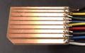
Fake SDcard - example 1
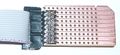
Fake SDcard - example 2


| |||||||||||||||||||||||||||||||||||||||||||||||||||||||||||||||||||||||||||||||||||||||||||||||||||||||||||||||||||||||||||||||||||||||||||||||||||||||||||||||||||||||||||||
