SPIway: Difference between revisions
Jump to navigation
Jump to search
m (→Pinout) |
m (→Pinout) |
||
| Line 6: | Line 6: | ||
=== Pinout === | === Pinout === | ||
<div style="float:right">[[File:MX25L1006E Pinout.png|200px|thumb|left|MX25L1006E Pinout]]<br />[[File:25X10CLYA1 Pinout.png|200px|thumb|left|25X10CLYA1 Pinout]]<br />[[File:MX25L25635FMI-10G Pinout.png|200px|thumb|left|MX25L25635FMI-10G Pinout]]<br /> | <div style="float:right">[[File:MX25L1006E Pinout.png|200px|thumb|left|[[MX25L1006E]] Pinout]]<br />[[File:25X10CLYA1 Pinout.png|200px|thumb|left|[[25X10CLYA1]] Pinout]]<br />[[File:MX25L25635FMI-10G Pinout.png|200px|thumb|left|[[MX25L25635FMI-10G]] Pinout]]<br /> | ||
[[File:SPIway.jpg|200px|thumb|left|Teensy 2.0++ SPIway Pinout]]</div> | [[File:SPIway.jpg|200px|thumb|left|Teensy 2.0++ SPIway Pinout]]</div> | ||
{| border="1" cellspacing="0" cellpadding="5" border="#999" class="wikitable" style="border:1px solid #999; border-collapse: collapse;" | {| border="1" cellspacing="0" cellpadding="5" border="#999" class="wikitable" style="border:1px solid #999; border-collapse: collapse;" | ||
Revision as of 20:28, 28 November 2013
SPIway
SPIway - Teensy++ 2.0 SPI flasher for PS4
Source: https://github.com/hjudges/NORway
Pinout

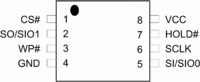
MX25L1006E Pinout

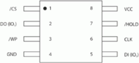
25X10CLYA1 Pinout

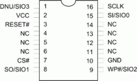
MX25L25635FMI-10G Pinout
File:SPIway.jpg
Teensy 2.0++ SPIway Pinout
| 8-Pin | 16-pin | Usage | Teensy++ 2.0 SPIway |
Description |
|---|---|---|---|---|
| - | 1 | SIO3 | B5 | 8pin: Not Available - not used / 16pin: Serial Data Input & Output (for 4xI/O read mode) |
| 8 | 2 | VCC | +5V pad | +3V DC Power Supply |
| 7 | 3 | HOLD#/RESET# | B6 | 8pin: Hold, to pause the device without deselecting the device / 16pin: Hardware Reset Pin Active low |
| - | 4 | NC | NC | No Connection |
| - | 5 | NC | NC | No Connection |
| - | 6 | NC | NC | No Connection |
| 1 | 7 | CS# | B0 | Chip Select |
| 2 | 8 | SO/SIO1 | B3 | Serial Data Output (for 1 x I/O) or Serial Data Input & Output (for 2x I/O or 4x I/O read mode) |
| 3 | 9 | WP#/SIO2 | B4 | Write Protection: connect to GND or Serial Data Input & Output (for 4x I/O read mode) |
| 4 | 10 | GND | GND | Ground |
| - | 11 | NC | NC | No Connection |
| - | 12 | NC | NC | No Connection |
| - | 13 | NC | NC | No Connection |
| - | 14 | NC | NC | No Connection |
| 5 | 15 | SI/SIO0 | B2 | Serial Data Input (for 1 x I/O) or Serial Data Input & Output (for 2x I/O or 4x I/O read mode) |
| 6 | 16 | SCLK | B1 | Clock Input |
Use short wires, esp. if you are not adding the 0.1µF capacitor between ground and vcc as close as possible to the chip
| |||||||||||||||||||||||||||||||||||||||||||||||||||||||||||||||||||
