DualShock 3: Difference between revisions
m (→Ribbon Circuit Boards: mine) |
|||
| Line 314: | Line 314: | ||
=== Ribbon Circuit Boards === | === Ribbon Circuit Boards === | ||
{| class="wikitable" border="1" | |||
|+ Ribbon Circuit Boards Compatibility | |||
! PCB !! Ribbon !! Notes | |||
|- | |||
| MSU_VX4_0.10 || SA1Q189A || | |||
|} | |||
==== SA1Q135A ==== | ==== SA1Q135A ==== | ||
<gallery> | <gallery> | ||
Revision as of 00:42, 11 August 2017
| This article is marked for rewrite/restructuring in proper wiki format. You can help PS3 Developer wiki by editing it. |
Overview

CECH-ZC2J, CECH-ZC2JA, CECH-ZC2JB (CECH-ZC2U, CECH-ZC2E, CECH-ZC2J, CECH-ZC2H, CECH-ZC2M)
CECHZC2 (SCPH-98050, CBEH-1018: prototype)
FCC ID: AK8CECHZC2
ID: 409B-CECHZC2
MIC listings:
- 007WWCUL0622 February 28, 2011 (CECHZC2JA)
- 007WWCUL0622 April 12, 2012 (CECHZC2JA)
- 007WWCUL0622 September 20, 2012 (CECHZC2JA)
- 007-AB0090 April 26, 2013 (CECHZC2JA)
- 007WWCUL0686 June 16, 2011 (CECHZC2JB)
- 007WWCUL0241 October 3, 2007 (CECHZC2J)
- 007WWCUL0281 April 22, 2008 (CECHZC2J)
- 007WWCUL0324 October 21, 2008 (CECHZC2J)
- 007WWCUL0477 February 24, 2010 (CECHZC2J)
Anatel:
- 0516156223 30/03/2015 (CECHZC2M)
- 1745106223 13/06/2013 (CECHZC2M, CECHZC2U)
Patent:
| Model Number | Name description | Release date | Note |
|---|---|---|---|
| CECHZC2J | 2007, November 11 | Japan | |
| CECHZC2J SS | 2008, March 6 | Japan | |
| CECH-ZC2J MB | 2009, October 29 | Japan | |
| CECH-ZC2J DR | 2009, October 29 | Japan | |
| CECH-ZC2J LW | 2010, July 29 | Japan | |
| CECH-ZC2J CP | 2010, November 18 | Japan | |
| CECH-ZC2J YB | 2011, April 21 | Japan | |
| CECH-ZC2J JG | 2011, February 24 | Japan | |
| CEJH-15017 | TALES OF XILLIA®2 X cross Edition | 2012, November 1 | Japan |
| CEJH-15020 | God of War: Ascension bundle | 2013, March 14 | Japan |
| CECH-ZC2J MY | 2013, June 20 | Japan | |
| CECH-ZC2J VT | Vita TV edition (White) | 2013, November 14 | Japan |
| CECH-ZC2J CY | 2013, December 19 | Japan | |
- Regions (last letter of the "model number"):
- E Europe
- H Hong Kong
- HK Hong Kong
- J Japan
- K Korea
- R Russia
- T Taiwan
- U United States
- M Mexico (seen in Anatel.br)
- Revisions (small letter + number after the "model number")
Components
Printed Circuit Board (PCB)
The table below shows one representative model for every revision from PP4 up to VX6. Is not included VX7 because is very different
| Sixaxis | DualShock 3 | ||||||
|---|---|---|---|---|---|---|---|
| PP4 | V2 | VX 1 | V3.5X | VX3 | VX4 | VX5 | VX6 |
| MSU PP4.0 5 | MSU V2 2.12 | MSU VX 1.03 | MSU V3.5X 1.12 | MSU VX3 0.07 | MSU VX4 0.09 | MSU VX5 0.06 | MSU VX6 0.06 |
.jpg) .jpg)
|
.jpg) .jpg)
|
.jpg) .jpg)
|
.jpg) .jpg)
|
.jpg) .jpg)
|
.jpg) .jpg)
|
.jpg) .jpg)
|
.jpg) .jpg)
|
| Controller Type | Prototype | Sixaxis | DualShock 3 | ASUKA | |||||||||||
|---|---|---|---|---|---|---|---|---|---|---|---|---|---|---|---|
| TestPoints Relocations | 0 | 1 | 2 | 3 | 4 | 5 | 6 | 7 | 8 | NO | |||||
| Board Model | PP1 | PP4- | PP4+ | V2 | V2.5 | VX | V3.5X | VX3 | VX4 | VX5 | VX6 | VX7 | VX8 | 1.06 | 1.07 |
| Total amount of testpoints | 26 | 26 | 26 | 4 | |||||||||||
| USB +5V | TP4 ? | TP1 | TP1 | TP1 | TP1 | TP1 | TP1 | TP1 | TP1 | TP1 | TP1 | UNL | T207 | ||
| USB Data - | TP2 | TP2 | TP2 | TP2 | TP2 | TP2 | TP2 | TP2 | TP2 | TP2 | TP2 | UNL | T206 | ||
| USB Data + | TP3 | TP3 | TP3 | TP3 | TP3 | TP3 | TP3 | TP3 | TP3 | TP3 | TP3 | UNL | T205 | ||
| USB Ground (or Common Ground) | 4x GND | TP21, TP22, TP23, TP24 | TP4, TP5, TP6, TP7 | 4x GND | 4x UNL | T509 | |||||||||
| Battery USB power good ? | TP6 ? | N/A | |||||||||||||
| Battery charge start ? | TP7 ? | N/A | |||||||||||||
| Battery charge setpoint pre ? | TP9 | N/A | |||||||||||||
| Battery charge setpoint post ? | TP64 ? | N/A | |||||||||||||
| Battery status 1 ? | TP8 ? | TP8 | TP15 | TP31 | UNL | ||||||||||
| Battery status 2 ? | TP10 ? | TP9 | TP9 | TP32 | UNL | ||||||||||
| 2.8V Switched. Power for vibration motors | 3.0V ? | N/A | TP42 | TP8 | TP25 | UNL | T501 | ||||||||
| Bluetooth Module, unknown | TP10 | TP11 | TP26 | T504 ? | |||||||||||
| 2.8V Standby. Power for MCU, EEPROM, BT, |
TP10 | TP10 | TP62 | TP62 | TP62 | TP51 | TP11 | TP11 | TP10 | TP29 | T507 | T507 | |||
| 2.8V Switched. Power for Accelerometer and Gyroscope | TP12 | TP12 | TP28 | UNL | T506 | T506 | |||||||||
| 2.8V Switched. Power for 4x Stick |
TP13 | TP13 | TP13 | TP27 | UNL | T505 | |||||||||
| 3.7V Battery + | TP5 ? | TP14 | TP14 | TP14 | TP30 | UNL | T508 | ||||||||
| COM 1. Common Line for Analog |
TP21 ? | TP17 | TP17 | TP25 | TP25 | TP25 | TP17 | TP17 | TP17 | TP17 | TP14 | UNL | T101 | ||
| COM 2. Common Line for Analog |
TP22 ? | TP18 | TP18 | TP26 | TP26 | TP26 | TP18 | TP18 | TP18 | TP18 | TP15 | UNL | T102 | ||
| COM 3. Common Line for Digital |
TP60 | TP60 | N/A | ||||||||||||
| TP19 ? | TP27 ? | TP19 ? | TP19 ? | TP19 ? | TP19 ? | TP16 ? | UNL | T103 | |||||||
| TP20 ? | TP28 ? | TP20 ? | TP20 ? | TP20 ? | TP20 ? | TP17 ? | UNL | T104 | |||||||
| TP21 ? | TP29 ? | TP21 ? | TP21 ? | TP21 ? | TP21 ? | TP18 ? | UNL | T105 | |||||||
| TP22 ? | TP30 ? | TP22 ? | TP22 ? | TP22 ? | TP22 ? | TP19 ? | UNL | T106 | |||||||
| Toshiba T6UN6EFG pin 69, unknown | TP23 | N/A ? | TP23 | TP23 | TP23 | TP20 | |||||||||
| Toshiba T6UN2EFG pin 68 | TP24 | TP24 | TP31 ? | TP31 ? | TP31 ? | TP23 ? | N/A | ||||||||
| Unknown (Toshiba T6UN6EFG pin 67 ?) | TP25 | TP25 | TP37 ? | TP37 ? | TP37 ? | TP29 ? | N/A | ||||||||
| Unknown | TP36 | TP36 | TP44 ? | TP44 ? | TP44 ? | TP36 ? | N/A | ||||||||
| TP26 | TP26 | TP32 | TP32 | TP32 | TP24 | N/A | |||||||||
| TP27 | TP27 | TP33 | TP33 | TP33 | TP25 | N/A | |||||||||
| TP28 | TP28 | TP34 | TP34 | TP34 | TP26 | N/A | |||||||||
| TP29 | TP29 | TP35 | TP35 | TP35 | TP27 | N/A | |||||||||
| TP30 | TP30 | TP36 | TP36 | TP36 | TP28 | N/A | |||||||||
| TP37 | TP37 | TP38 | TP38 | TP38 | TP30 | N/A | |||||||||
| TP31 | TP31 | TP39 | TP39 | TP39 | TP31 | N/A | |||||||||
| TP38 | TP38 | TP40 | TP40 | TP40 | TP32 | N/A | |||||||||
| TP39 | TP39 | TP41 | TP41 | TP41 | TP33 | N/A | |||||||||
| TP32 | TP32 | TP42 | TP42 | TP42 | TP34 | N/A | |||||||||
| TP33 | TP33 | TP43 | TP43 | TP43 | TP35 | N/A | |||||||||
| TP34 | TP34 | TP45 | TP45 | TP45 | TP37 | N/A | |||||||||
| TP41 | TP41 | TP46 | TP46 | TP46 | TP38 | N/A | |||||||||
| TP35 | TP35 | TP47 | TP47 | TP47 | TP39 | N/A | |||||||||
| TP42 | TP42 | TP48 | TP48 | TP48 | TP40 | N/A | |||||||||
| TP43 | TP43 | TP49 | TP49 | TP49 | TP41 | N/A | |||||||||
| TP44 | TP44 | TP50 | TP50 | TP50 | TP42 | N/A | |||||||||
| Bluetooth module (SPI unknown 1) | S-CL ? | CON | TP74 | TP47 | UNL | TP23 | UNL ? | ||||||||
| Bluetooth module (SPI unknown 2) | S-CS ? | CON | TP75 | TP48 | UNL | TP24 | UNL ? | ||||||||
| Bluetooth module (SPI unknown 3) | S-MI ? | CON | TP76 | TP49 | UNL | TP25 | UNL ? | ||||||||
| Bluetooth module (SPI unknown 4) | S-MO ? | CON | TP77 | TP50 | UNL | TP26 | UNL ? | ||||||||
| Accelerometer Y-Axis (raw signal) | TP32 | TP32 | TP8 | UNL | T302 | ||||||||||
| Accelerometer X-Axis (raw signal) | TP33 | TP33 | TP9 | UNL | T303 | ||||||||||
| Accelerometer Z-Axis (raw signal) | TP34 | TP34 | TP10 | UNL | T301 | ||||||||||
| Accelerometer Y-Axis (filtered signal) | TP54 ? | TP35 | TP35 | TP11 | UNL | T305 | |||||||||
| Accelerometer X-Axis (filtered signal) | TP55 ? | TP36 | TP36 | TP12 | UNL | T306 | |||||||||
| Accelerometer Z-Axis (filtered signal) | TP56 ? | TP37 | TP37 | TP13 | UNL | T304 | |||||||||
| Gyroscope (filtered signal) | TP40 | TP40 | TP33 | ||||||||||||
| Gyroscope (raw signal) | TP26 ? | TP41 | TP41 | TP34 | |||||||||||
| Enable Small motor | TP54 | N/A | N/A | ||||||||||||
| Enable Big motor | TP15 | N/A | N/A | ||||||||||||
Prototypes
PP1
- Models
- MSU PP 1.2 MAIN ALPS
Notable differences include
- Plastic finish being glossy
- Player LEDs arranged in a square around the USB-mini port and includes a clear plastic shield over the opening for the LEDs
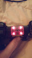
- PS Home button is clear and retains a red LED underneath it
- L2 and R2 buttons are present as opposed to Triggers
- Motors are present
- Battery inside contains a sticker with the date 2006/3/2 and the model of the batter appears to be longer
- Lacks the pinhole and switch on the back
- Label on the front reads Gセンサー搭載 Stick動作せず once roughly translated it reads Powered by the G Sensor, without moving the stick
- Label on the back reads 0604KATA2
- Toshiba MCU is on top side of the board (in all the other models is at bottom)
- The main board was designed without gyroscope and without accelerometer sensors, it has a "children board" sticked on top manufactured by HDK (the first 2 letters of the "HDK" brand are partially visible etched on copper on the children board), this children board includes the accelerometer HDK HAAM 325B [1]. It outputs 3 signals on the 3 white wires "hand made" soldered to the TOSHIBA controller to retrieve the axis data. The other "hand made" soldered component uses 3 wires (black = ground, red = volts, and yellow soldered to TP26) seems to be a Murata ENC-03R Gyroscope Sensor [2]. It seems both components was integrated later in the circuit board of the controllers labeled "sixaxis"
Internally the Gyroscopic sensor for Sixaxis controllers is wired onto the board - presumably as a test for a sensor revision on a spare sample board. The sensor itself appears to be far from complete and very early. Windows (10) detects the controller when connected via USB; analog sticks do not get detected but all other buttons do. The controller does not work on DECHA00A/J units, but might work on DECR units or earlier.
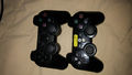
Front comparison next to a CECHZC2U
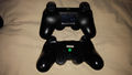
Back comparison next to a CECHZC2U
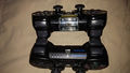
Top comparison to a CECHZC2U
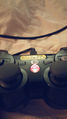
Front LED
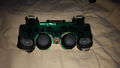
Top LEDs
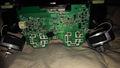
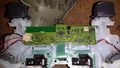
Back of the Board
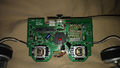
Front of the Board
Gyro Sensor. Click to see it in detail
Battery found inside


Sixaxis
PP4
- Models
- MSUPP4.0 5
- MSUPP4.0 9
- MSUPP4.0 11
MSU PP4.0 5
(Top)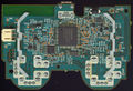
MSU PP4.0 5
(Bottom)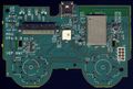
MSU PP4.0 9
(Top)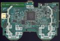
MSU PP4.0 9
(Bottom)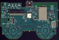
MSU PP4.0 11
(Top)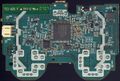
MSU PP4.0 11
(Bottom)
.jpg)
.jpg)
.jpg)
.jpg)
V2
- Models
- MSU_V2 2.12
- MSU_V2 2.14
- MSU_V2.5 1.05
Notable differences
- Sticks potenciometers with 4 legs, previous versions had 3 legs
MSU_V2 2.12
(Top)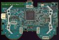
MSU_V2 2.12
(Bottom)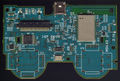
MSU_V2 2.14
(Top)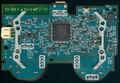
MSU_V2 2.14
(Bottom)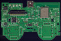
MSU_V2.5 1.05
(Top)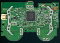
MSU_V2.5 1.05
(Bottom)
.jpg)
.jpg)
.jpg)
.jpg)
DualShock 3
VX 1
- Models
- MSU_VX 1.03
Notable differences
- Added vibration motors
- Updated wireless module
MSU_VX 1.03
(Top)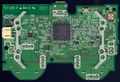
MSU_VX 1.03
(Bottom)
VX3.5X
- Models
- MSU_V3.5X 1.12
- MSU_V3.5X 1.14
Notable differences
- Pressure connector for the buttons membrane
MSU_V3.5X 1.12
(Top)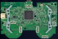
MSU_V3.5X 1.12
(Bottom)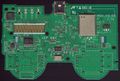
MSU_V3.5X 1.14
(Top)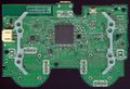
MSU_V3.5X 1.14
(Bottom)
Dualshock 3 digital buttons and LED's interfacing
MSU_V3.5X board
.jpg)
.jpg)

VX3
- Models
- MSU_VX3_0.07
- MSU_VX3_0.08
- MSU_VX3_0.11
MSU_VX3_0.07
(Top)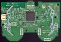
MSU_VX3_0.07
(Bottom)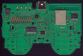
MSU_VX3_0.08
(Top)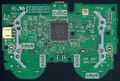
MSU_VX3_0.08
(Bottom)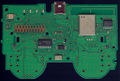
MSU_VX3_0.11
(Top)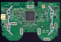
MSU_VX3_0.11
(Bottom)
.jpg)
.jpg)
.jpg)
.jpg)
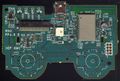
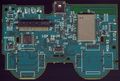
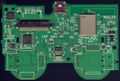
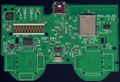
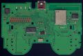
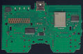
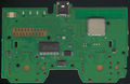
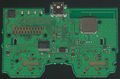
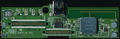
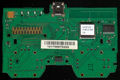
VX4
- Models
- MSU_VX4_0.09
- MSU_VX4_0.10
MSU_VX4_0.09
(Top)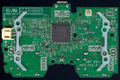
MSU_VX4_0.09
(Bottom)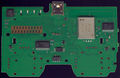
MSU_VX4_0.10
(Top)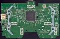
MSU_VX4_0.10
(Bottom)
.jpg)
.jpg)
VX5
- Models
- MSU_VX5_0.05
- MSU_VX5_0.06
Notable differences
- Updated wireless module
MSU_VX5_0.05
(Top)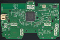
MSU_VX5_0.05
(Bottom)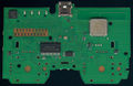
MSU_VX5_0.06
(Top)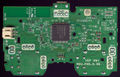
MSU_VX5_0.06
(Bottom)
.jpg)
.jpg)
VX6
- Models
- VX6_0.06
Notable differences
- Sticks potenciometers with 3 legs, previous versions had 4 legs
MSU_VX6_0.06
(Top)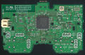
MSU_VX6_0.06
(Bottom)
VX7
- Models
- MSU_VX7_0.04
MSU_VX7_0.04
(Top)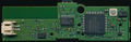
MSU_VX7_0.04
(Bottom)
Others
Asuka
The ASUKA boards made in china seems to be 3rd party (not sony official). At the time when was released sony was manufacturing the VX5 series... later sony continued with VX6, VX7, etc... ignoring the "ASUKA" labeling
- Models
- ASUKA REV: 1.06
- ASUKA REV: 1.07
ASUKA REV: 1.06
(Top)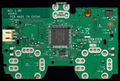
ASUKA REV: 1.06
(Bottom)
.jpg)
.jpg)
VX8 ?
There is not much info about this model, so is not clear if is the official VX8 or a third party clone of VX7
MSU_VX8_?.??
(Bottom)
.jpg)
MicroController Unit (MCU)
Toshiba T6UN6EFG
QFP package, 80pin
Submodels:
- Toshiba T6UN6EFG-001
- Toshiba T6UN6EFG-002
- Toshiba T6UN6EFG-003
| Pin # | Name | Port | Description |
|---|---|---|---|
| 1 | GND | To ground | |
| 2 | V_STBY | 2.8V Standby. Power for Toshiba T6UN6EFG, EEPROM, | |
| 3 | GND | To ground | |
| 4 | V_BATT | 2x Capacitor network to ground, and resistor to battery and Texas Instruments SN89062 pin 16 in VX4 boards | |
| 5 | V_STBY | 2.8V Standby. Power for Toshiba T6UN6EFG, EEPROM, | |
| 6 | SENSOR_ACCL_X | To acccelerometer X axis through resistor | |
| 7 | SENSOR_ACCL_Y | To acccelerometer Y axis through resistor | |
| 8 | SENSOR_ACCL_Z | To acccelerometer Z axis through resistor | |
| 9 | SENSOR_GYRO | To gyroscope through resistor | |
| 10 | V_STBY | 2.8V Standby. Power for Toshiba T6UN6EFG, EEPROM, | |
| 11 | SLAVES_RESET | Texas Instruments SN84001 pin 2, and ALPS 413A pin 5 through resistor network in VX4 boards | |
| 12 | GND | To ground | |
| 13 | BT_POWER_CTRL ? | Texas Instruments SN89062, pin 4 in VX4 boards | |
| 14 | BT_UART_1 ? | To BT module (ALPS 413A pin 8 in VX4 boards) through resistor | |
| 15 | BT_UART_2 ? | To BT module (ALPS 413A pin 6 in VX4 boards) through 4x resistor network | |
| 16 | BT_UART_3 ? | To BT module (ALPS 413A pin 9 in VX4 boards) through 4x resistor network | |
| 17 | BT_UART_4 ? | To BT module (ALPS 413A pin 7 in VX4 boards) | |
| 18 | BT_UNK_1 | To BT module (ALPS 413A pin 14 in VX4 boards) | |
| 19 | BT_UNK_2 | To BT module (ALPS 413A pin 28 in VX4 boards) | |
| 20 | GND | To ground | |
| 21 | V_STBY | 2.8V Standby. Power for Toshiba T6UN6EFG, EEPROM, | |
| 22 | GND | To ground | |
| 23 | LED_1 | To led 1 cathode through 4x resistor network (RN3 in VX4 boards) | |
| 24 | LED_2 | To led 2 cathode through 4x resistor network (RN3 in VX4 boards) | |
| 25 | LED_3 | To led 3 cathode through 4x resistor network (RN3 in VX4 boards) | |
| 26 | LED_4 | To led 4 cathode through 4x resistor network (RN3 in VX4 boards) | |
| 27 | Not connected ? (for the PS button backlight led in prototypes ?) | ||
| 28 | MOTOR_SMALL | Small Motor + (rumble) | |
| 29 | MOTOR_BIG | Big Motor + (rumble) | |
| 30 | EEPROM_SPI_CLOCK | EEPROM, pin 6 in VX4 boards | |
| 31 | EEPROM_SELECT | EEPROM, pin 1 in VX4 boards | |
| 32 | GND | To ground | |
| 33 | V_STBY | 2.8V Standby. Power for Toshiba T6UN6EFG, EEPROM, | |
| 34 | EEPROM_SPI_MOSI | EEPROM, pin 5 in VX4 boards | |
| 35 | EEPROM_SPI_MISO | EEPROM, pin 2 in VX4 boards | |
| 36 | STICKS_POWER_CTRL ? | Texas Instruments SN89062, pin 17 in VX4 boards | |
| 37 | LX_V ? | 4x Resistor network (RN8 in VX4 boards), and then 2x Capacitor network to ground (CN9 in VX4 boards), and to Texas Instruments SN84001 pin 21 in VX4 boards | |
| 38 | LY_V ? | 4x Resistor network (RN8 in VX4 boards), and then 2x Capacitor network to ground (CN9 in VX4 boards), and to Texas Instruments SN84001 pin 20 in VX4 boards | |
| 39 | RX_V ? | 4x Resistor network (RN8 in VX4 boards), and then 2x Capacitor network to ground (CN10 in VX4 boards), and to Texas Instruments SN84001 pin 19 in VX4 boards | |
| 40 | RY_V ? | 4x Resistor network (RN8 in VX4 boards), and then 2x Capacitor network to ground (CN10 in VX4 boards), and to Texas Instruments SN84001 pin 18 in VX4 boards | |
| 41 | BATT_CHARGE_SETPOINT | Texas Instruments SN89062, pin 21 in VX4 boards | |
| 42 | BATT_USB_POWER_GOOD ? | Texas Instruments SN89062, pin 5 in VX4 boards | |
| 43 | BATT_CHARGE_START ? | Texas Instruments SN89062, pin 2 in VX4 boards | |
| 44 | BATT_STATUS_1 ? | Texas Instruments SN89062, pin 10 in VX4 boards (and TP8 in VX4 boards) | |
| 45 | BATT_STATUS_2 ? | Texas Instruments SN89062, pin 12 in VX4 boards (and TP9 in VX4 boards) | |
| 46 | COM_3 | COM 3 (Common Line for Digital | |
| 47 | BUTTON_ANALOG_UP | ||
| 48 | BUTTON_ANALOG_RIGHT | ||
| 49 | BUTTON_ANALOG_DOWN | ||
| 50 | BUTTON_ANALOG_LEFT | ||
| 51 | V_STBY | 2.8V Standby. Power for Toshiba T6UN6EFG, EEPROM, | |
| 52 | GND | To ground | |
| 53 | BUTTON_ANALOG_L2 | ||
| 54 | BUTTON_ANALOG_L1 | ||
| 55 | Not connected ? (connected to something in PP1 and PP4 boards) | ||
| 56 | BUTTON_ANALOG_R2 | ||
| 57 | BUTTON_ANALOG_R1 | ||
| 58 | BUTTON_ANALOG_TRIANGLE | ||
| 59 | BUTTON_ANALOG_CIRCLE | ||
| 60 | BUTTON_ANALOG_CROSS | ||
| 61 | BUTTON_ANALOG_SQUARE | ||
| 62 | Not connected ? (connected to something in PP1 and PP4 boards) | ||
| 63 | Not connected ? (connected to something in PP1 and PP4 boards) | ||
| 64 | BUTTON_DIGITAL_SELECT | ||
| 65 | BUTTON_DIGITAL_L3 | ||
| 66 | BUTTON_DIGITAL_R3 | ||
| 67 | BUTTON_DIGITAL_START | ||
| 68 | BUTTON_DIGITAL_PLAYSTATION | ||
| 69 | To a testpoint (TP23 in VX4 boards), and 8.45K resistor to pin 74 | ||
| 70 | GND | To ground. It seems these pins were repurposed at some point | |
| 71 | GND | ||
| 72 | GND | ||
| 73 | V_STBY | 2.8V Standby. Power for Toshiba T6UN6EFG, EEPROM, | |
| 74 | 2x Capacitor network to ground, and NTC thermistor to standby power rail, and 8.45K resistor to pin 69 | ||
| 75 | COM_1 | 2x Capacitor network to ground, and to ribbon circuit board COM 1 pin (Common Line for Analog | |
| 76 | COM_2 | 2x Capacitor network to ground, and to ribbon circuit board COM 2 pin (Common Line for Analog | |
| 77 | LX | ||
| 78 | LY | ||
| 79 | RX | ||
| 80 | RY |
Memory
Seiko Instruments S-25C040A0I-T8T1G (EEPROM - 4Kb, CMOS, SPI)
Atmel AT24C08B-TH (EEPROM - 8kb, 2-Wire Serial /BT)
Sensors
Kionix KXPC4 (Accelerometer - 3-Axis)
DFN
Epson-Toyocom XV3500CB (Gyroscope Sensor)
Epson-Toyocom XV3500CB
Sticks
Two rotational potentiometers (variable resistors) are positioned below eack stick to meassure X and Y displacement. Current flows constantly through each one, and the amount of current is determined by the amount of resistance. Resistance is increased or decreased based on the position of the stick in a range from 0V up to 2.8V with center point at 1.4V
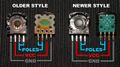
PS3 controller stick sealed pots with antidust protection, rotated externally by magnet field

Ribbon Circuit Boards
| PCB | Ribbon | Notes |
|---|---|---|
| MSU_VX4_0.10 | SA1Q189A |
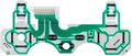
SA1Q135A
- Dualshock 3 Ribbon Circuit Board SA1Q135A.jpg
Dualshock 3 Ribbon Circuit Board SA1Q135A
SA1Q188A
Dualshock 3 Ribbon Circuit Board SA1Q188A

Battery
Li-Ion (Accupack)
LIP1359
3.7V 610mAh
MK11-2902
3.7V 610mAh
MK11-3020
3.7V 570mAh (typ. 610mAh)
Ways to tell if the controller is not original
.jpg)
- The SONY logo on the top of a counterfeit controller will not be aligned correctly with a originall controller.
- Different sticker label
- Counterfeit controllers have an extra screw on the back, hidden beneath the sticker.
- The label on the back of a counterfeit controller will be paper sticker.
- The label on the back of an official controller will have a thin layer of plastic over the paper sticker, giving it a matte finish and a more protected feel.
- The paper label on the back of a counterfeit controller will not be correctly aligned with the shape of the device on the back, as it was most likely put on by hand.
- Buttons
- The center Home button on a counterfeit controller will be marginally darker than the Home button on an official controller.
- Square, Triangle, Circle, and Cross buttons will be raised higher on a counterfeit controller.
- The colors of these face buttons will be dull, compared to the bright colors of an official DualShock 3.
- Sticks
- Compared to an official controller, the seams beneath the analog sticks where the bottom and top halves of the plastic meet will be sharp.
- Leds
- The LEDs lights on the controller that signify which Player it is controlling will not be flush with the outside shell. Official controllers are relatively level all the way across. Some controllers may have minor protrusion of the LEDs, though this should not be significant.
- When you turn on a counterfeit the controller, the flashing red lights on the outside will actually shine THROUGH the casing of the device, something that would never happen on an official product.
- Syncing
- If you have consistent trouble wirelessly syncing your controller to your PS3, the device may be counterfeit.
From: http://www.ps3hax.net/showthread.php?p=574042#post574042
Homebrew
- PS Seismograph 0.2.0 from Deroad:
I have updated my homebrew to 0.2.0. now it supports all tv resolution (old versions were only for 1080p/i tv)
This is a simple Seismograph for ps3. it uses all the axis of the first controller.
[Download]http://store.brewology.com/ahomebrew.php?brewid=177
[GIT] https://github.com/wargio/PS-Seismograph
[Forum] http://www.ps3hax.net/showthread.php?t=53698
[Forum] http://psx-scene.com/forums/content/ps-seismograph-0-2-0-deroad-3121/
[Blog] http://devram0.blogspot.it/
- Others : Jjolano's PS Vibe (3.55+?), PS Vibe Move Edition Deroad( or only ps move+ps eye compatible?), MultiMan: rumble and gyroscope function?
- See also Move Motion Controller page
PC Drivers
for use of controller on PC
- http://forums.pcsx2.net/Thread-XInput-Wrapper-for-DS3-and-Play-com-USB-Dual-DS2-Controller
- http://www.motioninjoy.com/download
- https://www.youtube.com/watch?v=FsUtQ8urmw0
- http://betterds3.ciebiera.net/
- http://xpadder.com/
- http://www.rapiro.com/downloads/ (Sony Dualshock 3 gamepad to work in Raspberry Pi on RAPIRO)
Related Hardware
USB host adapter
- http://www.hobbytronics.co.uk/usb-host/ps3-controller Connect a PS3 Dualshock Controller to the USB Host Board
Other
- nice PCB overview of revisions: http://forums.xbox-scene.com/lofiversion/index.php/t648322.html http://forums.xbox-scene.com/index.php?/topic/648322-ps3-controller-versions-and-tp-spots/ http://s50.photobucket.com/user/RDCXBG/library/PS3%20Six-Axis%20and%20DS3
| |||||||||||||