Search results
Jump to navigation
Jump to search
Create the page "Connector" on this wiki! See also the search results found.
Page title matches

File:HDMI Connector Pinout.svg [[Category:Hardware]]HDMI Connector Pinout(224 × 92 (26 KB)) - 09:55, 16 November 2012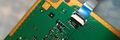
File:Service connector 3rd gen VERTIGO.jpg [[Category:Hardware]]PS3 Service Connector 3rd gen on [[VER-001|VERTIGO]](1,500 × 500 (109 KB)) - 05:39, 9 May 2021
File:PS3 Service Connector DYN-001.jpg [[Category:Hardware]]PS3 Service Connector DYN-001(64 × 77 (1 KB)) - 15:53, 8 May 2013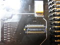
File:E3 - Panasonic PCB connector 50pin.jpg [[Category:Hardware]]E3 - Panasonic PCB connector 50pin(3,648 × 2,736 (2.41 MB)) - 01:38, 28 April 2012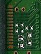
File:PS3 Service Connector JSD-001.jpg [[Category:Hardware]]PS3 Service Connector JSD-001(81 × 105 (4 KB)) - 15:53, 8 May 2013- |+PS3 PSU Control connector 3 pins428 bytes (60 words) - 02:30, 27 March 2021
- |+PS3 PSU Control connector 4 pins468 bytes (66 words) - 02:30, 27 March 2021
File:PS3 Service Connector MPX-001 12GB.jpg [[Category:Hardware]]PS3 Service Connector MPX-001 12GB(98 × 207 (4 KB)) - 15:52, 8 May 2013- |+PS3 PSU Control connector 5 pins486 bytes (67 words) - 02:31, 27 March 2021
File:PS3 Service Connector VER-001-small.jpg [[Category:Hardware]]PS3 Service Connector VER-001(87 × 120 (3 KB)) - 15:55, 8 May 2013
File:PS3 PinJIG Connector 3rd Generation DYN-001.jpg [[Category:Hardware]]PS3 Service Connector 3rd Generation DYN-001(37 × 61 (18 KB)) - 12:32, 8 May 2013
File:PS3 PinJIG Connector 3rd Generation SURTEES-03.jpg [[Category:Hardware]]PS3 Service Connector 3rd Generation SURTEES-03(41 × 62 (18 KB)) - 12:32, 8 May 2013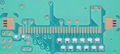
File:PS3 Service Connector 1st Generation COK-002.jpg [[Category:Hardware]]PS3 [[Service Connectors|Service Connector]] 1st Generation [[COK-00x#COK-002|COK-002]](3,268 × 1,458 (386 KB)) - 15:14, 8 May 2013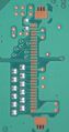
File:PS3 PinJIG Connector 1st Generation COK-002.jpg [[Category:Hardware]]PS3 Service Connector 1st Generation COK-002(1,724 × 3,270 (517 KB)) - 15:21, 8 May 2013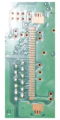
File:PS3 Service Connector 1st Generation COK-001.png [[Category:Hardware]]PS3 [[Service Connectors|Service Connector]] 1st Generation [[COK-00x#COK-001|COK-001]](500 × 1,000 (562 KB)) - 15:08, 6 June 2013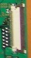
File:PS3 PinJIG Connector 1st Generation COOKIE-13.jpg [[Category:Hardware]]PS3 Service Connector 1st Generation COOKIE-13(105 × 195 (9 KB)) - 12:31, 8 May 2013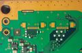
File:PS3 PinJIG Connector 2nd Generation DIA-001.jpg [[Category:Hardware]]PS3 Service Connector 2nd Generation DIA-001(1,656 × 1,080 (136 KB)) - 09:36, 5 January 2015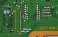
File:PCI connector JSD-001 SB and SC UART.jpg [[Category:Hardware]] 80 pins [[PCI]] connector on [[JSD-001]] motherboard, [[South Bridge]] and [[Syscon Hardware|Syscon]](1,200 × 778 (284 KB)) - 06:50, 9 May 2021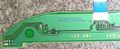
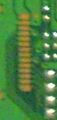
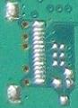
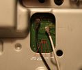
File:Power Eject board HSW-001 (Connector pin 1 detail).jpg Power Eject board HSW-001 (Connector pin 1 detail)[[Category:Hardware]](1,500 × 611 (187 KB)) - 17:46, 3 January 2015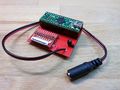
File:Teensy adapter Board for NANDway - DC connector for external 5V supply.jpg Teensy adapter Board for NANDway - DC connector for external 5V supply[[Category:Hardware]](3,264 × 2,448 (3.11 MB)) - 07:56, 9 January 2015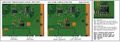
File:JSD-001 and JTP-001 USB connector TH3301 thermistor and DC switch IC to southbridge v2.jpg [[JSD-001]]/[[JTP-001]] [[USB]] connector [[Protection|TH3301 thermistor]] and DC switch IC to [[South Bridge]][[Cate(1,279 × 449 (126 KB)) - 07:47, 8 May 2014


Page text matches

File:RSX-HDMItransmitter-HDMIconnector.png [[Category:Hardware]]RSX to HDMI-transmitter to HDMI connector diagram ...s/# Cool UML Diagram, [RSX]->[HDMI transmitter], [HDMI transmitter]->[HDMI connector]</nowiki>(1,286 × 125 (21 KB)) - 17:38, 27 July 2011
File:RSX-MultiAVDA-MultiAVconnector.png [[Category:Hardware]]RSX to MultiAV DA to MultiAV connector diagram ...180;/class/# Cool UML Diagram, [RSX]->[MultiAV DA], [MultiAV DA]->[MultiAV connector]</nowiki>(1,219 × 125 (21 KB)) - 17:43, 27 July 2011
File:PS3 HDMI pinout.jpg [[Category:Hardware]]HDMI Connector Pinout(719 × 583 (95 KB)) - 00:00, 19 May 2014File:HDMI Connector Pinout.svg [[Category:Hardware]]HDMI Connector Pinout(224 × 92 (26 KB)) - 09:55, 16 November 2012File:PS3 Service Connector DYN-001.jpg [[Category:Hardware]]PS3 Service Connector DYN-001(64 × 77 (1 KB)) - 15:53, 8 May 2013File:PS3 Service Connector JSD-001.jpg [[Category:Hardware]]PS3 Service Connector JSD-001(81 × 105 (4 KB)) - 15:53, 8 May 2013File:PS3 Service Connector VER-001-small.jpg [[Category:Hardware]]PS3 Service Connector VER-001(87 × 120 (3 KB)) - 15:55, 8 May 2013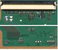
File:60pin-DB-CON.jpg [[Category:Hardware]]60pin DB Connector - bluray drive(823 × 710 (127 KB)) - 13:46, 12 July 2011File:E3 - Panasonic PCB connector 50pin.jpg [[Category:Hardware]]E3 - Panasonic PCB connector 50pin(3,648 × 2,736 (2.41 MB)) - 01:38, 28 April 2012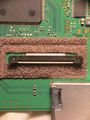
File:BD-460 laser pickup connector.jpg [[Category:Hardware]]BD-460 laser pickup connector(2,736 × 3,648 (1.08 MB)) - 21:37, 13 June 2015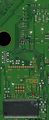
File:Bluray Drive Diagnostic Port 28pin on JSD-001.jpg [[Category:Hardware]] Service connector on [[JSD-001]](303 × 745 (115 KB)) - 05:41, 4 June 2021File:PS3 Service Connector MPX-001 12GB.jpg [[Category:Hardware]]PS3 Service Connector MPX-001 12GB(98 × 207 (4 KB)) - 15:52, 8 May 2013File:PS3 PinJIG Connector 1st Generation COK-002.jpg [[Category:Hardware]]PS3 Service Connector 1st Generation COK-002(1,724 × 3,270 (517 KB)) - 15:21, 8 May 2013File:PS3 PinJIG Connector 1st Generation COOKIE-13.jpg [[Category:Hardware]]PS3 Service Connector 1st Generation COOKIE-13(105 × 195 (9 KB)) - 12:31, 8 May 2013File:PS3 PinJIG Connector 2nd Generation DIA-001.jpg [[Category:Hardware]]PS3 Service Connector 2nd Generation DIA-001(1,656 × 1,080 (136 KB)) - 09:36, 5 January 2015File:PS3 PinJIG Connector 3rd Generation DYN-001.jpg [[Category:Hardware]]PS3 Service Connector 3rd Generation DYN-001(37 × 61 (18 KB)) - 12:32, 8 May 2013File:PS3 PinJIG Connector 3rd Generation SURTEES-03.jpg [[Category:Hardware]]PS3 Service Connector 3rd Generation SURTEES-03(41 × 62 (18 KB)) - 12:32, 8 May 2013File:Power Eject board HSW-001 (Connector pin 1 detail).jpg Power Eject board HSW-001 (Connector pin 1 detail)[[Category:Hardware]](1,500 × 611 (187 KB)) - 17:46, 3 January 2015File:Service connector 3rd gen VERTIGO.jpg [[Category:Hardware]]PS3 Service Connector 3rd gen on [[VER-001|VERTIGO]](1,500 × 500 (109 KB)) - 05:39, 9 May 2021- ...dentify pin1 by looking at HSW-001 board... the solution is to look at the connector in the other side of the ribbon cable (in other words... in the main mother ...ail).jpg|The blue text is wrong because this point is not related with the connector but this is actually pin 1 if you look at the motherboard and trace it alon1 KB (256 words) - 04:39, 19 July 2017
- ...'''. Toslink female surface connector pin 2 (Vcc) is tied with a pin of AV connector and both goes to a component labeled '''5A KC''' (transistor ?)1 KB (171 words) - 08:43, 20 July 2017
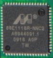
File:Marvel-Alaska-88E1118R.PNG righthand side goes to backside RJ/UTP connector(640 × 695 (707 KB)) - 11:58, 18 July 2011File:Teensy adapter Board for NANDway - DC connector for external 5V supply.jpg Teensy adapter Board for NANDway - DC connector for external 5V supply[[Category:Hardware]](3,264 × 2,448 (3.11 MB)) - 07:56, 9 January 2015- = PCI connector redesigned for PS3 slim models ? = On [[CECH-25xx]]/[[JSD-001]] the pinout of the PCI connector seems to differ from what is published in frontpage. See [https://www.psdev672 bytes (103 words) - 07:26, 9 May 2021
File:JSD-001 and JTP-001 USB connector TH3301 thermistor and DC switch IC to southbridge v2.jpg [[JSD-001]]/[[JTP-001]] [[USB]] connector [[Protection|TH3301 thermistor]] and DC switch IC to [[South Bridge]][[Cate(1,279 × 449 (126 KB)) - 07:47, 8 May 2014- {{PS3 PSU Control connector 5 pins}}192 bytes (24 words) - 02:39, 27 March 2021
File:Marvel Alaska 88E1310-NNB2.jpg righthand side goes to backside RJ/UTP connector(3,648 × 2,736 (924 KB)) - 21:19, 13 June 2015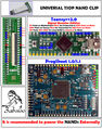
File:Universal NAND TSOP clip.jpg Note: this will not fit on the [[COK-002]] NAND next to the SATA connector(1,488 × 1,890 (944 KB)) - 04:47, 16 November 2014File:PCI connector JSD-001 SB and SC UART.jpg [[Category:Hardware]] 80 pins [[PCI]] connector on [[JSD-001]] motherboard, [[South Bridge]] and [[Syscon Hardware|Syscon]](1,200 × 778 (284 KB)) - 06:50, 9 May 2021- |+PS3 PSU Control connector 3 pins428 bytes (60 words) - 02:30, 27 March 2021
File:PS3 Service Connector 1st Generation COK-001.png [[Category:Hardware]]PS3 [[Service Connectors|Service Connector]] 1st Generation [[COK-00x#COK-001|COK-001]](500 × 1,000 (562 KB)) - 15:08, 6 June 2013File:PS3 Service Connector 1st Generation COK-002.jpg [[Category:Hardware]]PS3 [[Service Connectors|Service Connector]] 1st Generation [[COK-00x#COK-002|COK-002]](3,268 × 1,458 (386 KB)) - 15:14, 8 May 2013- *2-pins connector, disc load/eject motor (load+, load-) *14-pins connector (switches are located at pins 4,5,6)964 bytes (137 words) - 22:47, 20 March 2022
- ...inout_BGA_200_pads|Syscon]] pad R10<br>[[Service Connectors#CN4009|Service Connector]] (CN4009) pin 17 || Testpad ?. <abbr title="missing resistor>NC</abbr> || | 8 || BD_LED || BluRay connector (CN3221) pin 50 || Blue led ||2 KB (225 words) - 05:56, 18 October 2022
- |+PS3 PSU Control connector 4 pins468 bytes (66 words) - 02:30, 27 March 2021
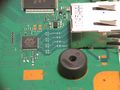
File:SC Serv Connector.JPG [[Syscon Hardware|Syscon]] [[Service Connectors|Service Connector]][[Category:Hardware]](1,772 × 1,516 (481 KB)) - 02:11, 12 June 2015- {{PS3 PSU Control connector 4 pins}}282 bytes (43 words) - 17:01, 27 March 2021
- |+PS3 PSU Control connector 5 pins486 bytes (67 words) - 02:31, 27 March 2021
- ** IC3802 LOW (main componentside with SATA connector, [[CELL BE]], [[RSX]] etc. next to [[Starship2]]) ** IC3803 HIGH (backside next to 60-pin BD ATA connector)3 KB (469 words) - 07:13, 17 April 2023
- {{PS3 PSU Control connector 4 pins}}347 bytes (46 words) - 02:50, 27 March 2021
- Has a 45-pin connector for the laser flat flex cable and thus needs the [[KEM-850]] drive. File:Superslim missing component close to SB.jpg|eMMC solder pads and service connector1 KB (169 words) - 17:40, 7 February 2023
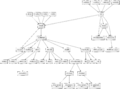
File:CECHC-COK-002-diagram.png ...transmitter], [MultiAV DA]->[MultiAV connector], [HDMI-transmitter]->[HDMI connector]</nowiki> [MultiAV DA]->[MultiAV connector](3,310 × 2,453 (512 KB)) - 13:48, 1 August 2011- File:SURTEES-03 8.jpg|Populated Communication Processor Connector File:SURTEES-03 9.jpg|Populated Syscon Service Connector1 KB (187 words) - 13:39, 19 May 2024
- ...[File:HDMI pads as seen on JTP-001 - (Mr.Dutch).jpg|200px|thumb|right|HDMI connector pads]]<br>[[File:RSX SKEMA.jpg|200px|thumb|right|RSX 41x41 pad layout]]<br> ...lcolors|#ccf}} CEC || {{pinio}} || Connected to [[Connectors#HDMI_Out|HDMI connector]] pin 13 ([https://en.wikipedia.org/wiki/Consumer_Electronics_Control Consu10 KB (1,146 words) - 07:31, 20 July 2022
- RS_SPDO_33 goes to layerhole to R2412 and goes directly to IC2409 (TOSLINK connector) RS_SPDO_33 goes to layerhole to R2412 and goes directly to IC2409 (TOSLINK connector)2 KB (250 words) - 08:38, 20 July 2017
- {{PS3 PSU Control connector 5 pins}}350 bytes (49 words) - 02:35, 27 March 2021

File:Progskeet v11.jpg [[Category:Hardware]]Progskeet 1.1 with 50pin zif connector and configurable power between 1.5V to 3.3V (to support 1.8V NANDs for exam(754 × 1,058 (170 KB)) - 05:17, 4 December 2011- * CRTC -> Encoder -> Connector * It seems that head A is connected to HDMI connector.2 KB (325 words) - 03:05, 3 February 2014
- {{PS3 PSU Control connector 5 pins}}395 bytes (63 words) - 02:37, 27 March 2021
- * MECHA_INT (pad E2) Connected to BluRay Drive connector (CN3221) pin 46 * MC_DET (pad E4) Connected to MultiCard Reader connector (CN3219) pin 142 KB (244 words) - 02:42, 18 October 2022
- {{PS3 PSU Control connector 5 pins}}441 bytes (71 words) - 23:45, 27 January 2022
- {{PS3 PSU Control connector 4 pins}}473 bytes (74 words) - 02:46, 27 March 2021
- {{PS3 PSU Control connector 3 pins}}414 bytes (65 words) - 02:40, 27 March 2021
- {{PS3 PSU Control connector 4 pins}}485 bytes (77 words) - 02:37, 9 September 2021
- {{PS3 PSU Control connector 5 pins}}466 bytes (76 words) - 02:39, 27 March 2021
- ...tor and DC switch IC to southbridge v2.jpg|[[JSD-001]]/[[JTP-001]] [[USB]] connector [[Protection|TH3301 thermistor]] and DC switch IC to [[South Bridge]] ...ed in:<br/>• "A" connector (host): connected to the signal ground<br>• "B" connector (device): not connected3 KB (387 words) - 06:16, 1 July 2023
- ...ile:BD-460 laser pickup connector.jpg|200px|thumb|left|BD-460 laser pickup connector]]</div>569 bytes (83 words) - 21:36, 13 June 2015
- {{PS3 PSU Control connector 3 pins}}394 bytes (53 words) - 02:41, 27 March 2021
- * Motherboard connector CN101443 bytes (56 words) - 03:28, 31 December 2014
- ....com/ps3/index.php?search=connector&fulltext=Search&title=Special%3ASearch Connector] ||3 KB (406 words) - 13:57, 22 November 2021
- ...Communication Processor|CP Board]] can be used to connect via the Service Connector to the PS3 ...e problem is, that the CN4403 has over 100 pins and the COOKIE/COK Service Connector only 30 ;).7 KB (1,257 words) - 04:09, 4 May 2023
- {{PS3 PSU Control connector 4 pins}}520 bytes (83 words) - 02:49, 27 March 2021
- {{PS3 PSU Control connector 4 pins}}572 bytes (82 words) - 13:05, 15 April 2024
- | 8 || BD_LED || BluRay Connector, pin 13 || Blue led || Connects to blue LED over eject switch. | 10 || {{cellcolors|#CC3333|white}} +5V_EVER || [[Power Supply]] Connector (CN101), pin 1 || VCC || 5V Standby2 KB (302 words) - 18:23, 5 December 2021
- ...[File:HDMI pads as seen on JTP-001 - (Mr.Dutch).jpg|200px|thumb|right|HDMI connector pads]]<br>[[File:RSX SKEMA.jpg|200px|thumb|right|RSX 41x41 pad layout]]</di | A2 || TX2+_25 || Connected to D2+ HDMI connector6 KB (897 words) - 08:45, 19 October 2022
- {{PS3 PSU Control connector 4 pins}}533 bytes (85 words) - 02:45, 27 March 2021
- Unlike PPX-001, this board has a 45-pin connector for the laser flat flex cable, just like earlier super slim motherboards di713 bytes (106 words) - 16:54, 10 February 2023
- {{PS3 PSU Control connector 4 pins}}519 bytes (74 words) - 02:43, 27 March 2021
- {{PS3 PSU Control connector 4 pins}}531 bytes (87 words) - 02:44, 27 March 2021
- Unlike earlier super slim boards and [[PQX-001]], this board has a 40-pin connector for the laser flat flex cable.759 bytes (112 words) - 09:20, 10 February 2023
- Has a 45-pin connector for the laser flat flex cable and thus needs the [[KEM-850]] drive.900 bytes (124 words) - 17:41, 7 February 2023
- ...ply]] Connector (CN101), pin 1 || VCC || 5V Standby line from power supply connector CN101, the pin named 5V_EVER on motherboard and 5VSB on power supply3 KB (386 words) - 18:25, 5 December 2021
- {{PS3 PSU Control connector 4 pins}}849 bytes (146 words) - 02:48, 27 March 2021
- ! Used on !! Type of Connector | [[MPU-501]] ([[CEB-2040]]) || CN6504: Headerpins<br />CN6507: ZIF Connector21 KB (2,729 words) - 06:05, 1 July 2023
- The [[TMR-520]] board connects the [[TCP-520]] board to the [[PCI]] connector of the PS3 motherboard. Cytology uses 160 pins, Cookie uses 70 or 80 pins b727 bytes (104 words) - 16:52, 22 April 2021
- ...that can send signals to the [[Move Motion Controller]] using a "special" connector. *"move controller" mini connector (8 pins)3 KB (393 words) - 12:44, 14 November 2023
- {{PS3 PSU Control connector 5 pins}}724 bytes (116 words) - 02:38, 27 March 2021
- {{PS3 PSU Control connector 3 pins}}1 KB (170 words) - 02:42, 27 March 2021
- Controller Main PCB, Top Electro-Mechanical Electro-Mechanical Connector 1 Jack - Mini USB, Right Angle Thru Hole Controller Main PCB, Top Electro-Mechanical Electro-Mechanical Connector 1 Pin Header - Shrouded, Right Angle SMD8 KB (951 words) - 08:21, 30 September 2017
- ...|| Connected to [[MultiAV]] [[Connectors#AV_Multi_Out_pinout_-_CN2401_12P|connector]] pin 4 (Cb/Pb/Blue) through 750ohm resistor ...|| Connected to [[MultiAV]] [[Connectors#AV_Multi_Out_pinout_-_CN2401_12P|connector]] pin 1 (Y/Green) through 750ohm resistor15 KB (1,981 words) - 19:11, 21 March 2023
- {{PS3 PSU Control connector 5 pins}}1 KB (162 words) - 02:36, 27 March 2021
- Has a 45-pin connector for the laser flat flex cable and thus needs the [[KEM-850]] drive.1 KB (157 words) - 17:41, 7 February 2023
- == Connector, Square type 12P == Used as [[MultiAV]] connector <br />12 KB (1,842 words) - 04:30, 13 October 2022
- ...|| Connected to [[MultiAV]] [[Connectors#AV_Multi_Out_pinout_-_CN2401_12P|connector]] pin 4 (Cb/Pb/Blue) through 750ohm resistor ? ...|| Connected to [[MultiAV]] [[Connectors#AV_Multi_Out_pinout_-_CN2401_12P|connector]] pin 1 (Y/Green) through 750ohm resistor ?11 KB (1,527 words) - 07:52, 19 October 2022
- *2-pin connector1 KB (162 words) - 22:47, 20 March 2022
- *[[CN301 60p]] (Bluraydrive I/O Connector) -> to [[Motherboard_Revisions|Motherboard]]1 KB (180 words) - 20:42, 9 May 2014
- * 24p (Bluraydrive I/O Connector) -> to [[Motherboard_Revisions|Motherboard]]1 KB (193 words) - 01:30, 15 September 2017
- *CECHB00 (full PS2 BC) - 3 hours runtime. Has a broken BD-drive connector on the motherboard. Using noBD CFW.1 KB (215 words) - 00:16, 23 May 2024
- *[[CN301 60p]] (Bluraydrive I/O Connector) -> to [[Motherboard_Revisions|Motherboard]]1 KB (183 words) - 20:13, 14 September 2018
- Has a 40-pin connector for the laser flat flex cable, just like [[RTX-001]] and [[PPX-001]].1 KB (197 words) - 16:51, 10 February 2023
- ...ower switch from the Fat models has been completely removed, and the mains connector changed from the three pin IEC 60320 C14 to the two pin IEC 60320 C8. The c1 KB (172 words) - 15:32, 30 October 2023
- {{PS3 PSU Control connector 4 pins}}1 KB (208 words) - 02:46, 27 March 2021
- * 24p (Bluraydrive I/O Connector) -> to [[Motherboard_Revisions|Motherboard]]1 KB (190 words) - 01:29, 10 May 2014
- Has a 40-pin connector for the laser flat flex cable, just like [[REX-001]] and [[PPX-001]].1 KB (205 words) - 16:51, 10 February 2023
- *[[CN301 60p]] (Bluraydrive I/O Connector) -> to [[Motherboard_Revisions|Motherboard]]1 KB (199 words) - 20:11, 14 September 2018
- ...rs|#ff0000}} 5V_EVER || Input 5v standby rail, from power supply (pin 1 of connector CN101) ...the HDMI connector, it have a thick copper trace for a voltage of the HDMI connector)>transistor</abbr>13 KB (1,679 words) - 01:48, 15 June 2022
- *[[CN301 60p]] (Bluraydrive I/O Connector) -> to [[Motherboard_Revisions|Motherboard]]1 KB (209 words) - 20:11, 14 September 2018
- Slaveboard/Adaptorboard connector, 50 pins2 KB (225 words) - 14:10, 25 May 2015
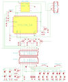
File:SYSCON SWx JTP-001 JSD-001 HSW-001 CN101.jpg ...or JSD-001, SYSCON SW2-30x series, Switches board HSW-001, and 4 pins PSU connector (CN101) for PSU models APS-270 or EADP-200DB<br>(1,635 × 1,954 (528 KB)) - 08:21, 19 July 2017- ...P-001 or JSD-001, SYSCON SW-x series, Switch board HSW-001, and 4 pins PSU connector (CN101) for PSU models APS-270 or EADP-200DB ...transistor, the transistor is activated by a volts signal from PIN1 of the connector, but the motherboard doesnt send this signal, see {{discussion}}13 KB (2,279 words) - 03:57, 20 July 2017


.jpg)