Search results
Jump to navigation
Jump to search
Create the page "Switch" on this wiki! See also the search results found.
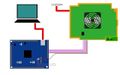
File:Console-only.jpg [[Category:Hardware]]Progskeet - Console-only powered, using R7 switch and 3.3V wire(640 × 400 (23 KB)) - 09:33, 5 May 2013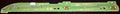
File:1-881-946-11.jpg HSW-001 Switch board (1-881-946-11)(3,016 × 340 (416 KB)) - 10:15, 11 June 2017- **Disc chucking switch. [[Template:Syscon_pinout_BGA_200_pads|Mullion Pin L15]] (DISC_CHUCK) **Disc 8cm detection switch [[Template:Syscon_pinout_BGA_200_pads|Mullion Pin B2 ]] (DISC_OUT8_SW)964 bytes (137 words) - 22:47, 20 March 2022
- ! On [[Motherboard_Revisions|Motherboard]] !! On [[Switch_boards|Switch board]] ...a [https://en.wikipedia.org/wiki/Pulse-width_modulation PWM] signal to the switch board ?2 KB (225 words) - 05:56, 18 October 2022
- {{{{{|safesubst:}}}#switch:none |{{{{{|safesubst:}}}#switch: {{lc:{{{2|}}}}} | none | asis | link | lnone =none }}4 KB (345 words) - 19:52, 14 December 2012
- |type={{#switch:{{{demolevel|{{#ifeq:{{PROTECTIONLEVEL:edit}}-{{PROTECTIONLEVEL:move}}|-sys ...n a high-risk template or message,|high-risk template}} is indefinitely {{#switch:{{{demolevel|{{#ifeq:{{PROTECTIONLEVEL:edit}}-{{PROTECTIONLEVEL:move}}|-sys3 KB (330 words) - 02:08, 10 January 2012
- ! On [[Motherboard_Revisions|Motherboard]] !! On [[Switch_boards|Switch board]] ...x]], pin 12 || 4x CONTOUR LEDs || Permanently inactive by default.<br />On Switch board is connected to a transistor driving 3 LEDs: TWO BLUE AND ONE RED.2 KB (302 words) - 18:23, 5 December 2021
- {{#switch:{{{type|}}} {{#switch:{{{type|}}}2 KB (247 words) - 05:48, 21 April 2015
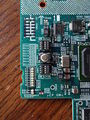
File:TMR-520 1-871-647-11 A Detail 1 (SW).jpg [[Category:Hardware]][[TMR-520]] [[1-871-647-11]] detail 1 SWITCH ([[DECR-1000]])(3,672 × 4,896 (4.87 MB)) - 04:43, 31 December 2014- {{#switch: {{SUBPAGENAME}}182 bytes (16 words) - 12:50, 14 February 2014
- |<span style="display:none">{{#time:Ym|{{{1}}}}}</span>{{#switch: -->|<span style="display:none">{{#time:Ymd|{{{1}}}}}</span>{{#switch:731 bytes (84 words) - 23:56, 12 December 2012
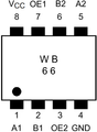
File:TC7WB66FK(TE85R).png ...re]]IC5005, TC7WB66FK(TE85R) (low on-resistance, high-speed CMOS2-bit bus switch), part no. 6-701-979-01, SSOP8(579 × 787 (30 KB)) - 05:22, 25 July 2011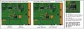
File:JSD-001 and JTP-001 USB connector TH3301 thermistor and DC switch IC to southbridge v2.jpg ...01]]/[[JTP-001]] [[USB]] connector [[Protection|TH3301 thermistor]] and DC switch IC to [[South Bridge]][[Category:Hardware]](1,279 × 449 (126 KB)) - 07:47, 8 May 2014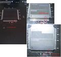
File:E3-Flasher 2012 actual defects!.jpg ...2, sd-card not working, usb E3 update not possible, maybe dualboot CFW-OFW switch without function(2,221 × 2,095 (1.22 MB)) - 05:50, 13 November 2012- {{#switch: {{SUBPAGENAME}}254 bytes (26 words) - 05:52, 1 February 2014
- {{#switch:{{{type|}}} | [[File:{{#switch:{{{type|}}}1 KB (148 words) - 06:04, 1 February 2014
- | {{#switch:{{{gc|<#not a Unicode code point#>}}} | #default=<span style="font-size:{{{size|unexp}}}">{{#switch:{{{use|}}}1 KB (142 words) - 06:42, 1 February 2014
- ...ly it can be enabled by connecting this pin to 5VSB through a 1k resistor">Switch</abbr> main output428 bytes (60 words) - 02:30, 27 March 2021
- ! On [[Motherboard_Revisions|Motherboard]] !! On [[Switch_boards|Switch board]] ...| 4x CONTOUR LEDs, transistor base pin || The transistor is located in the switch board and drives 2 LEDs with currentlimitor resistors of 3K {{ohm}} (red le3 KB (386 words) - 18:25, 5 December 2021
- {{#switch: }}<!--End switch--><noinclude>[[Category:Templates]]1 KB (125 words) - 13:07, 14 February 2014

.jpg)
.png)
