Search results
Jump to navigation
Jump to search
Create the page "Connector" on this wiki! See also the search results found.
Page title matches

File:HDMI Connector Pinout.svg [[Category:Hardware]]HDMI Connector Pinout(224 × 92 (26 KB)) - 09:55, 16 November 2012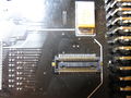
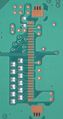
File:E3 - Panasonic PCB connector 50pin.jpg [[Category:Hardware]]E3 - Panasonic PCB connector 50pin(3,648 × 2,736 (2.41 MB)) - 01:38, 28 April 2012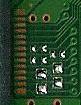
File:PS3 Service Connector JSD-001.jpg [[Category:Hardware]]PS3 Service Connector JSD-001(81 × 105 (4 KB)) - 15:53, 8 May 2013
File:Service connector 3rd gen VERTIGO.jpg [[Category:Hardware]]PS3 Service Connector 3rd gen on [[VER-001|VERTIGO]](1,500 × 500 (109 KB)) - 05:39, 9 May 2021
File:PS3 Service Connector DYN-001.jpg [[Category:Hardware]]PS3 Service Connector DYN-001(64 × 77 (1 KB)) - 15:53, 8 May 2013
File:PS3 Service Connector VER-001-small.jpg [[Category:Hardware]]PS3 Service Connector VER-001(87 × 120 (3 KB)) - 15:55, 8 May 2013- |+PS3 PSU Control connector 3 pins428 bytes (60 words) - 02:30, 27 March 2021
- |+PS3 PSU Control connector 4 pins468 bytes (66 words) - 02:30, 27 March 2021
File:PS3 Service Connector MPX-001 12GB.jpg [[Category:Hardware]]PS3 Service Connector MPX-001 12GB(98 × 207 (4 KB)) - 15:52, 8 May 2013- |+PS3 PSU Control connector 5 pins486 bytes (67 words) - 02:31, 27 March 2021
File:PS3 PinJIG Connector 1st Generation COK-002.jpg [[Category:Hardware]]PS3 Service Connector 1st Generation COK-002(1,724 × 3,270 (517 KB)) - 15:21, 8 May 2013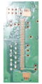
File:PS3 Service Connector 1st Generation COK-001.png [[Category:Hardware]]PS3 [[Service Connectors|Service Connector]] 1st Generation [[COK-00x#COK-001|COK-001]](500 × 1,000 (562 KB)) - 15:08, 6 June 2013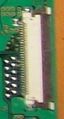
File:PS3 PinJIG Connector 1st Generation COOKIE-13.jpg [[Category:Hardware]]PS3 Service Connector 1st Generation COOKIE-13(105 × 195 (9 KB)) - 12:31, 8 May 2013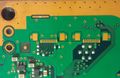
File:PS3 PinJIG Connector 2nd Generation DIA-001.jpg [[Category:Hardware]]PS3 Service Connector 2nd Generation DIA-001(1,656 × 1,080 (136 KB)) - 09:36, 5 January 2015
File:PS3 PinJIG Connector 3rd Generation DYN-001.jpg [[Category:Hardware]]PS3 Service Connector 3rd Generation DYN-001(37 × 61 (18 KB)) - 12:32, 8 May 2013
File:PS3 PinJIG Connector 3rd Generation SURTEES-03.jpg [[Category:Hardware]]PS3 Service Connector 3rd Generation SURTEES-03(41 × 62 (18 KB)) - 12:32, 8 May 2013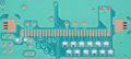
File:PS3 Service Connector 1st Generation COK-002.jpg [[Category:Hardware]]PS3 [[Service Connectors|Service Connector]] 1st Generation [[COK-00x#COK-002|COK-002]](3,268 × 1,458 (386 KB)) - 15:14, 8 May 2013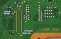
File:PCI connector JSD-001 SB and SC UART.jpg [[Category:Hardware]] 80 pins [[PCI]] connector on [[JSD-001]] motherboard, [[South Bridge]] and [[Syscon Hardware|Syscon]](1,200 × 778 (284 KB)) - 06:50, 9 May 2021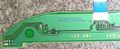
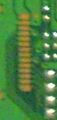
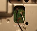
File:Power Eject board HSW-001 (Connector pin 1 detail).jpg Power Eject board HSW-001 (Connector pin 1 detail)[[Category:Hardware]](1,500 × 611 (187 KB)) - 17:46, 3 January 2015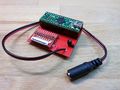
File:Teensy adapter Board for NANDway - DC connector for external 5V supply.jpg Teensy adapter Board for NANDway - DC connector for external 5V supply[[Category:Hardware]](3,264 × 2,448 (3.11 MB)) - 07:56, 9 January 2015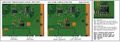
File:JSD-001 and JTP-001 USB connector TH3301 thermistor and DC switch IC to southbridge v2.jpg [[JSD-001]]/[[JTP-001]] [[USB]] connector [[Protection|TH3301 thermistor]] and DC switch IC to [[South Bridge]][[Cate(1,279 × 449 (126 KB)) - 07:47, 8 May 2014


Page text matches

File:RSX-HDMItransmitter-HDMIconnector.png [[Category:Hardware]]RSX to HDMI-transmitter to HDMI connector diagram ...s/# Cool UML Diagram, [RSX]->[HDMI transmitter], [HDMI transmitter]->[HDMI connector]</nowiki>(1,286 × 125 (21 KB)) - 17:38, 27 July 2011
File:RSX-MultiAVDA-MultiAVconnector.png [[Category:Hardware]]RSX to MultiAV DA to MultiAV connector diagram ...180;/class/# Cool UML Diagram, [RSX]->[MultiAV DA], [MultiAV DA]->[MultiAV connector]</nowiki>(1,219 × 125 (21 KB)) - 17:43, 27 July 2011
File:PS3 HDMI pinout.jpg [[Category:Hardware]]HDMI Connector Pinout(719 × 583 (95 KB)) - 00:00, 19 May 2014File:HDMI Connector Pinout.svg [[Category:Hardware]]HDMI Connector Pinout(224 × 92 (26 KB)) - 09:55, 16 November 2012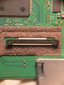
File:BD-460 laser pickup connector.jpg [[Category:Hardware]]BD-460 laser pickup connector(2,736 × 3,648 (1.08 MB)) - 21:37, 13 June 2015File:PS3 Service Connector DYN-001.jpg [[Category:Hardware]]PS3 Service Connector DYN-001(64 × 77 (1 KB)) - 15:53, 8 May 2013File:PS3 Service Connector JSD-001.jpg [[Category:Hardware]]PS3 Service Connector JSD-001(81 × 105 (4 KB)) - 15:53, 8 May 2013File:PS3 Service Connector VER-001-small.jpg [[Category:Hardware]]PS3 Service Connector VER-001(87 × 120 (3 KB)) - 15:55, 8 May 2013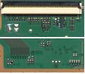
File:60pin-DB-CON.jpg [[Category:Hardware]]60pin DB Connector - bluray drive(823 × 710 (127 KB)) - 13:46, 12 July 2011File:E3 - Panasonic PCB connector 50pin.jpg [[Category:Hardware]]E3 - Panasonic PCB connector 50pin(3,648 × 2,736 (2.41 MB)) - 01:38, 28 April 2012File:PS3 Service Connector MPX-001 12GB.jpg [[Category:Hardware]]PS3 Service Connector MPX-001 12GB(98 × 207 (4 KB)) - 15:52, 8 May 2013
File:Bluray Drive Diagnostic Port 28pin on JSD-001.jpg [[Category:Hardware]] Service connector on [[JSD-001]](303 × 745 (115 KB)) - 05:41, 4 June 2021File:PS3 PinJIG Connector 3rd Generation SURTEES-03.jpg [[Category:Hardware]]PS3 Service Connector 3rd Generation SURTEES-03(41 × 62 (18 KB)) - 12:32, 8 May 2013File:PS3 PinJIG Connector 1st Generation COK-002.jpg [[Category:Hardware]]PS3 Service Connector 1st Generation COK-002(1,724 × 3,270 (517 KB)) - 15:21, 8 May 2013File:PS3 PinJIG Connector 1st Generation COOKIE-13.jpg [[Category:Hardware]]PS3 Service Connector 1st Generation COOKIE-13(105 × 195 (9 KB)) - 12:31, 8 May 2013File:PS3 PinJIG Connector 2nd Generation DIA-001.jpg [[Category:Hardware]]PS3 Service Connector 2nd Generation DIA-001(1,656 × 1,080 (136 KB)) - 09:36, 5 January 2015File:PS3 PinJIG Connector 3rd Generation DYN-001.jpg [[Category:Hardware]]PS3 Service Connector 3rd Generation DYN-001(37 × 61 (18 KB)) - 12:32, 8 May 2013File:Power Eject board HSW-001 (Connector pin 1 detail).jpg Power Eject board HSW-001 (Connector pin 1 detail)[[Category:Hardware]](1,500 × 611 (187 KB)) - 17:46, 3 January 2015File:Service connector 3rd gen VERTIGO.jpg [[Category:Hardware]]PS3 Service Connector 3rd gen on [[VER-001|VERTIGO]](1,500 × 500 (109 KB)) - 05:39, 9 May 2021- ...dentify pin1 by looking at HSW-001 board... the solution is to look at the connector in the other side of the ribbon cable (in other words... in the main mother ...ail).jpg|The blue text is wrong because this point is not related with the connector but this is actually pin 1 if you look at the motherboard and trace it alon1 KB (256 words) - 04:39, 19 July 2017
- ...'''. Toslink female surface connector pin 2 (Vcc) is tied with a pin of AV connector and both goes to a component labeled '''5A KC''' (transistor ?)1 KB (171 words) - 08:43, 20 July 2017
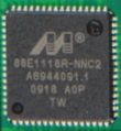
File:Marvel-Alaska-88E1118R.PNG righthand side goes to backside RJ/UTP connector(640 × 695 (707 KB)) - 11:58, 18 July 2011File:Teensy adapter Board for NANDway - DC connector for external 5V supply.jpg Teensy adapter Board for NANDway - DC connector for external 5V supply[[Category:Hardware]](3,264 × 2,448 (3.11 MB)) - 07:56, 9 January 2015- = PCI connector redesigned for PS3 slim models ? = On [[CECH-25xx]]/[[JSD-001]] the pinout of the PCI connector seems to differ from what is published in frontpage. See [https://www.psdev672 bytes (103 words) - 07:26, 9 May 2021
File:JSD-001 and JTP-001 USB connector TH3301 thermistor and DC switch IC to southbridge v2.jpg [[JSD-001]]/[[JTP-001]] [[USB]] connector [[Protection|TH3301 thermistor]] and DC switch IC to [[South Bridge]][[Cate(1,279 × 449 (126 KB)) - 07:47, 8 May 2014- {{PS3 PSU Control connector 5 pins}}192 bytes (24 words) - 02:39, 27 March 2021
File:Marvel Alaska 88E1310-NNB2.jpg righthand side goes to backside RJ/UTP connector(3,648 × 2,736 (924 KB)) - 21:19, 13 June 2015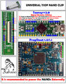
File:Universal NAND TSOP clip.jpg Note: this will not fit on the [[COK-002]] NAND next to the SATA connector(1,488 × 1,890 (944 KB)) - 04:47, 16 November 2014File:PCI connector JSD-001 SB and SC UART.jpg [[Category:Hardware]] 80 pins [[PCI]] connector on [[JSD-001]] motherboard, [[South Bridge]] and [[Syscon Hardware|Syscon]](1,200 × 778 (284 KB)) - 06:50, 9 May 2021- |+PS3 PSU Control connector 3 pins428 bytes (60 words) - 02:30, 27 March 2021
File:PS3 Service Connector 1st Generation COK-001.png [[Category:Hardware]]PS3 [[Service Connectors|Service Connector]] 1st Generation [[COK-00x#COK-001|COK-001]](500 × 1,000 (562 KB)) - 15:08, 6 June 2013File:PS3 Service Connector 1st Generation COK-002.jpg [[Category:Hardware]]PS3 [[Service Connectors|Service Connector]] 1st Generation [[COK-00x#COK-002|COK-002]](3,268 × 1,458 (386 KB)) - 15:14, 8 May 2013- *2-pins connector, disc load/eject motor (load+, load-) *14-pins connector (switches are located at pins 4,5,6)964 bytes (137 words) - 22:47, 20 March 2022
- ...inout_BGA_200_pads|Syscon]] pad R10<br>[[Service Connectors#CN4009|Service Connector]] (CN4009) pin 17 || Testpad ?. <abbr title="missing resistor>NC</abbr> || | 8 || BD_LED || BluRay connector (CN3221) pin 50 || Blue led ||2 KB (225 words) - 05:56, 18 October 2022
- |+PS3 PSU Control connector 4 pins468 bytes (66 words) - 02:30, 27 March 2021
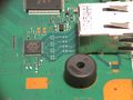
File:SC Serv Connector.JPG [[Syscon Hardware|Syscon]] [[Service Connectors|Service Connector]][[Category:Hardware]](1,772 × 1,516 (481 KB)) - 02:11, 12 June 2015- {{PS3 PSU Control connector 4 pins}}282 bytes (43 words) - 17:01, 27 March 2021
- |+PS3 PSU Control connector 5 pins486 bytes (67 words) - 02:31, 27 March 2021
- ** IC3802 LOW (main componentside with SATA connector, [[CELL BE]], [[RSX]] etc. next to [[Starship2]]) ** IC3803 HIGH (backside next to 60-pin BD ATA connector)3 KB (469 words) - 07:13, 17 April 2023
- {{PS3 PSU Control connector 4 pins}}347 bytes (46 words) - 02:50, 27 March 2021
- File:SURTEES-03 8.jpg|Populated Communication Processor Connector File:SURTEES-03 9.jpg|Populated Syscon Service Connector1 KB (187 words) - 16:45, 21 March 2023
- Has a 45-pin connector for the laser flat flex cable and thus needs the [[KEM-850]] drive. File:Superslim missing component close to SB.jpg|eMMC solder pads and service connector1 KB (169 words) - 17:40, 7 February 2023
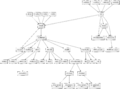
File:CECHC-COK-002-diagram.png ...transmitter], [MultiAV DA]->[MultiAV connector], [HDMI-transmitter]->[HDMI connector]</nowiki> [MultiAV DA]->[MultiAV connector](3,310 × 2,453 (512 KB)) - 13:48, 1 August 2011- ...[File:HDMI pads as seen on JTP-001 - (Mr.Dutch).jpg|200px|thumb|right|HDMI connector pads]]<br>[[File:RSX SKEMA.jpg|200px|thumb|right|RSX 41x41 pad layout]]<br> ...lcolors|#ccf}} CEC || {{pinio}} || Connected to [[Connectors#HDMI_Out|HDMI connector]] pin 13 ([https://en.wikipedia.org/wiki/Consumer_Electronics_Control Consu10 KB (1,146 words) - 07:31, 20 July 2022
- RS_SPDO_33 goes to layerhole to R2412 and goes directly to IC2409 (TOSLINK connector) RS_SPDO_33 goes to layerhole to R2412 and goes directly to IC2409 (TOSLINK connector)2 KB (250 words) - 08:38, 20 July 2017
- {{PS3 PSU Control connector 5 pins}}350 bytes (49 words) - 02:35, 27 March 2021

File:Progskeet v11.jpg [[Category:Hardware]]Progskeet 1.1 with 50pin zif connector and configurable power between 1.5V to 3.3V (to support 1.8V NANDs for exam(754 × 1,058 (170 KB)) - 05:17, 4 December 2011- * CRTC -> Encoder -> Connector * It seems that head A is connected to HDMI connector.2 KB (325 words) - 03:05, 3 February 2014
- {{PS3 PSU Control connector 5 pins}}395 bytes (63 words) - 02:37, 27 March 2021
- * MECHA_INT (pad E2) Connected to BluRay Drive connector (CN3221) pin 46 * MC_DET (pad E4) Connected to MultiCard Reader connector (CN3219) pin 142 KB (244 words) - 02:42, 18 October 2022


.jpg)