Service Connectors: Difference between revisions
Jump to navigation
Jump to search
mNo edit summary |
|||
| (15 intermediate revisions by 4 users not shown) | |||
| Line 1: | Line 1: | ||
JTAG/UART/SPI/Diagnostic I/O used in Sony repair centers if a PS4 | JTAG/UART/SPI/Diagnostic I/O used in Sony repair centers if a PS4 could not be fixed by software. | ||
== Preproduction Generation == | |||
=== Syscon === | |||
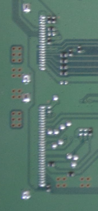
<div style="float:right">[[File:CVN-001-ServConn.png|200px|thumb|left|[[DUH-D1000xA_series]][[CVN-001]] img1]]<br/> </div> | <div style="float:right">[[File:CVN-001-ServConn.png|200px|thumb|left|[[DUH-D1000xA_series]][[CVN-001]] img1]]<br/> </div> | ||
[[A00- | |||
[[A00-COL]] | |||
{| border="1" cellspacing="0" cellpadding="5" border="#999" class="wikitable" style="border:1px solid #999; border-collapse: collapse;" | {| border="1" cellspacing="0" cellpadding="5" border="#999" class="wikitable" style="border:1px solid #999; border-collapse: collapse;" | ||
|- bgcolor="#cccccc" | |- bgcolor="#cccccc" | ||
| Line 71: | Line 76: | ||
|- | |- | ||
| 32 || || | | 32 || || | ||
|} | |} | ||
[[Aeolia]] | === Southbridge === | ||
See [[Aeolia]]. | |||
{| border="1" cellspacing="0" cellpadding="5" border="#999" class="wikitable" style="border:1px solid #999; border-collapse: collapse;" | {| border="1" cellspacing="0" cellpadding="5" border="#999" class="wikitable" style="border:1px solid #999; border-collapse: collapse;" | ||
|- bgcolor="#cccccc" | |- bgcolor="#cccccc" | ||
| Line 118: | Line 125: | ||
|- | |- | ||
| 20 || || | | 20 || || | ||
|} | |||
=== PCIe === | |||
[[PCIe]] [[CVN-001]] | |||
<div style="float:right">[[File:PCI-Service_Connectors.png|200px|thumb|left|[[DUH-D1000xA_series]][[CVN-001]] img1]]<br/> </div> | |||
{| border="1" cellspacing="0" cellpadding="5" border="#999" class="wikitable" style="border:1px solid #999; border-collapse: collapse;" | |||
|- bgcolor="#cccccc" | |||
! Pin !! Name !! Description | |||
|- | |||
| 1 || || | |||
|- | |||
| 2 || || | |||
|- | |||
| 3 || || | |||
|- | |||
| 4 || || | |||
|- | |||
| 5 || || | |||
|- | |||
| 6 || || | |||
|- | |||
| 7 || || | |||
|- | |||
| 8 || || | |||
|- | |||
| 9 || || | |||
|- | |||
| 10 || || | |||
|- | |||
| 11 || || | |||
|- | |||
| 12 || || | |||
|- | |||
| 13 || || | |||
|- | |||
| 14 || || | |||
|- | |||
| 15 || || | |||
|- | |- | ||
|} | | 16 || || | ||
|- | |||
| 17 || || | |||
|- | |||
| 18 || || | |||
|- | |||
| 19 || || | |||
|- | |||
| 20 || || | |||
|} | |||
{| border="1" cellspacing="0" cellpadding="5" border="#999" class="wikitable" style="border:1px solid #999; border-collapse: collapse;" | {| border="1" cellspacing="0" cellpadding="5" border="#999" class="wikitable" style="border:1px solid #999; border-collapse: collapse;" | ||
|- bgcolor="#cccccc" | |- bgcolor="#cccccc" | ||
| Line 139: | Line 192: | ||
| 5 || || | | 5 || || | ||
|- | |- | ||
| 6 || | | 6 || || | ||
|- | |- | ||
| 7 || | | 7 || || | ||
|- | |- | ||
| 8 || | | 8 || || | ||
|- | |- | ||
| 9 || || | | 9 || || | ||
| Line 153: | Line 206: | ||
| 12 || || | | 12 || || | ||
|- | |- | ||
| 13 || | | 13 || || | ||
|- | |- | ||
| 14 || || | | 14 || || | ||
| Line 161: | Line 214: | ||
| 16 || || | | 16 || || | ||
|- | |- | ||
| 17 || | | 17 || || | ||
|- | |- | ||
| 18 || || | | 18 || || | ||
| Line 168: | Line 221: | ||
|- | |- | ||
| 20 || || | | 20 || || | ||
|} | |||
== First Generation == | |||
=== Syscon === | |||
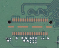
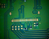
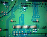
<div style="float:right">[[File:CUH-10xxA - SAA-001 - 30 pins port - img1.jpg|200px|thumb|left|[[CUH-10xxA]] [[SAA-001]] pads3/30 pins - img1]]<br />[[File:CUH-10xxA - SAA-001 - 30 pins port - img2.jpg|200px|thumb|left|[[CUH-10xxA]] [[SAA-001]] pads3/30 pins - img2]]</div> | |||
See [[A01-COL]]. | |||
{| border="1" cellspacing="0" cellpadding="5" border="#999" class="wikitable" style="border:1px solid #999; border-collapse: collapse;" | |||
|- bgcolor="#cccccc" | |||
! Pin !! Name !! Description | |||
|- | |||
| 1 || VCC? || | |||
|- | |||
| 2 || NC || No connection | |||
|- | |||
| 3 || || == pin 1 | |||
|- | |||
| 4 || || | |||
|- | |- | ||
| 21 || | | 5 || || | ||
|- | |||
| 6 || Gnd || Internal ground | |||
|- | |||
| 7 || I2C || I2C bus (100 kHz clock) -> HDR-D pin 2 | |||
|- | |||
| 8 || || -> HDR-D pin 1 | |||
|- | |||
| 9 || Gnd || Internal ground | |||
|- | |||
| 10 || SC-P70 || | |||
|- | |||
| 11 || || | |||
|- | |||
| 12 || SC-P72 || | |||
|- | |||
| 13 || || | |||
|- | |||
| 14 || Gnd || Internal ground | |||
|- | |||
| 15 || SC-P12 || | |||
|- | |||
| 16 || SC-P11 || | |||
|- | |||
| 17 || SC-P51 || | |||
|- | |||
| 18 || Gnd || Internal ground | |||
|- | |||
| 19 || -> SB? || | |||
|- | |||
| 20 || -> SB? || | |||
|- | |||
| 21 || -> SB? || | |||
|- | |- | ||
| 22 || | | 22 || SC-P40 (TOOL0) open circuit || | ||
|- | |- | ||
| 23 || | | 23 || Gnd || Internal ground | ||
|- | |- | ||
| 24 || | | 24 || SC-RESET# || | ||
|- | |- | ||
| 25 || | | 25 || GND|| Internal ground | ||
|- | |- | ||
| 26 || || | | 26 || || | ||
| Line 183: | Line 289: | ||
| 27 || || | | 27 || || | ||
|- | |- | ||
| 28 || || | | 28 || SC-P122 || | ||
|- | |||
| 29 || SC-P121 || | |||
|- | |||
| 30 || NC || No connection | |||
|} | |||
=== Southbridge === | |||
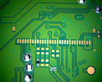
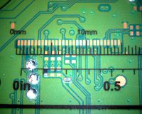
<div style="float:right">[[File:CUH-10xxA - SAA-001 - 20 pins port - img1.jpg|200px|thumb|left|[[CUH-10xxA]] [[SAA-001]] pads2/20 pins - img1]]<br />[[File:CUH-10xxA - SAA-001 - 20 pins port - img2.jpg|200px|thumb|left|[[CUH-10xxA]] [[SAA-001]] pads2/20 pins - img2]]</div> | |||
See [[Aeolia]], [[Southbridge]] debug. | |||
{| border="1" cellspacing="0" cellpadding="5" border="#999" class="wikitable" style="border:1px solid #999; border-collapse: collapse;" | |||
|- bgcolor="#cccccc" | |||
! Pin !! Name !! Description | |||
|- | |||
| 1 || VCC? || | |||
|- | |||
| 2 || Gnd || Internal ground | |||
|- | |||
| 3 || || | |||
|- | |||
| 4 || Gnd || Internal ground | |||
|- | |||
| 5 || || | |||
|- | |||
| 6 || || | |||
|- | |||
| 7 || || | |||
|- | |||
| 8 || Gnd || Internal ground | |||
|- | |||
| 9 || || | |||
|- | |||
| 10 || | |||
|- | |||
| 11 || Gnd || Internal ground | |||
|- | |||
| 12 || SB-20/S (SDIO?) || probably for eMMC | |||
|- | |||
| 13 || Gnd || Internal ground | |||
|- | |||
| 14 || SB-19/R (SDIO?) || | |||
|- | |||
| 15 || SB SDIO? || | |||
|- | |||
| 16 || SB SDIO? || | |||
|- | |||
| 17 || SB SDIO? || | |||
|- | |||
| 18 || SB SDIO? || | |||
|- | |- | ||
| | | 19 || Gnd || Internal ground | ||
|- | |- | ||
| | | 20 || NC || | ||
|- | |- | ||
|} | |} | ||
== | == Second Generation == | ||
* TODO | * TODO | ||
Latest revision as of 00:29, 2 February 2022
JTAG/UART/SPI/Diagnostic I/O used in Sony repair centers if a PS4 could not be fixed by software.
Preproduction Generation[edit | edit source]
Syscon[edit | edit source]
| Pin | Name | Description |
|---|---|---|
| 1 | ||
| 2 | ||
| 3 | ||
| 4 | ||
| 5 | ||
| 6 | ||
| 7 | ||
| 8 | ||
| 9 | ||
| 10 | ||
| 11 | ||
| 12 | ||
| 13 | ||
| 14 | ||
| 15 | ||
| 16 | ||
| 17 | ||
| 18 | ||
| 19 | ||
| 20 | ||
| 21 | ||
| 22 | ||
| 23 | ||
| 24 | ||
| 25 | ||
| 26 | ||
| 27 | ||
| 28 | ||
| 29 | ||
| 30 | ||
| 31 | ||
| 32 |
Southbridge[edit | edit source]
See Aeolia.
| Pin | Name | Description |
|---|---|---|
| 1 | ||
| 2 | ||
| 3 | ||
| 4 | ||
| 5 | ||
| 6 | ||
| 7 | ||
| 8 | ||
| 9 | ||
| 10 | ||
| 11 | ||
| 12 | ||
| 13 | ||
| 14 | ||
| 15 | ||
| 16 | ||
| 17 | ||
| 18 | ||
| 19 | ||
| 20 |
PCIe[edit | edit source]
| Pin | Name | Description |
|---|---|---|
| 1 | ||
| 2 | ||
| 3 | ||
| 4 | ||
| 5 | ||
| 6 | ||
| 7 | ||
| 8 | ||
| 9 | ||
| 10 | ||
| 11 | ||
| 12 | ||
| 13 | ||
| 14 | ||
| 15 | ||
| 16 | ||
| 17 | ||
| 18 | ||
| 19 | ||
| 20 |
| Pin | Name | Description |
|---|---|---|
| 1 | ||
| 2 | ||
| 3 | ||
| 4 | ||
| 5 | ||
| 6 | ||
| 7 | ||
| 8 | ||
| 9 | ||
| 10 | ||
| 11 | ||
| 12 | ||
| 13 | ||
| 14 | ||
| 15 | ||
| 16 | ||
| 17 | ||
| 18 | ||
| 19 | ||
| 20 |
First Generation[edit | edit source]
Syscon[edit | edit source]
See A01-COL.
| Pin | Name | Description |
|---|---|---|
| 1 | VCC? | |
| 2 | NC | No connection |
| 3 | == pin 1 | |
| 4 | ||
| 5 | ||
| 6 | Gnd | Internal ground |
| 7 | I2C | I2C bus (100 kHz clock) -> HDR-D pin 2 |
| 8 | -> HDR-D pin 1 | |
| 9 | Gnd | Internal ground |
| 10 | SC-P70 | |
| 11 | ||
| 12 | SC-P72 | |
| 13 | ||
| 14 | Gnd | Internal ground |
| 15 | SC-P12 | |
| 16 | SC-P11 | |
| 17 | SC-P51 | |
| 18 | Gnd | Internal ground |
| 19 | -> SB? | |
| 20 | -> SB? | |
| 21 | -> SB? | |
| 22 | SC-P40 (TOOL0) open circuit | |
| 23 | Gnd | Internal ground |
| 24 | SC-RESET# | |
| 25 | GND | Internal ground |
| 26 | ||
| 27 | ||
| 28 | SC-P122 | |
| 29 | SC-P121 | |
| 30 | NC | No connection |
Southbridge[edit | edit source]
See Aeolia, Southbridge debug.
| Pin | Name | Description |
|---|---|---|
| 1 | VCC? | |
| 2 | Gnd | Internal ground |
| 3 | ||
| 4 | Gnd | Internal ground |
| 5 | ||
| 6 | ||
| 7 | ||
| 8 | Gnd | Internal ground |
| 9 | ||
| 10 | ||
| 11 | Gnd | Internal ground |
| 12 | SB-20/S (SDIO?) | probably for eMMC |
| 13 | Gnd | Internal ground |
| 14 | SB-19/R (SDIO?) | |
| 15 | SB SDIO? | |
| 16 | SB SDIO? | |
| 17 | SB SDIO? | |
| 18 | SB SDIO? | |
| 19 | Gnd | Internal ground |
| 20 | NC |
Second Generation[edit | edit source]
- TODO
