Service Connectors: Difference between revisions
Jump to navigation
Jump to search
| Line 6: | Line 6: | ||
<imgur>I2NazzQ.png</imgur> | <imgur>I2NazzQ.png</imgur> | ||
[[File:5_Pin_Service_Layout_Proto.jpg]] | |||
== Second Connector (24 Pins) == | == Second Connector (24 Pins) == | ||
Revision as of 16:03, 15 January 2023
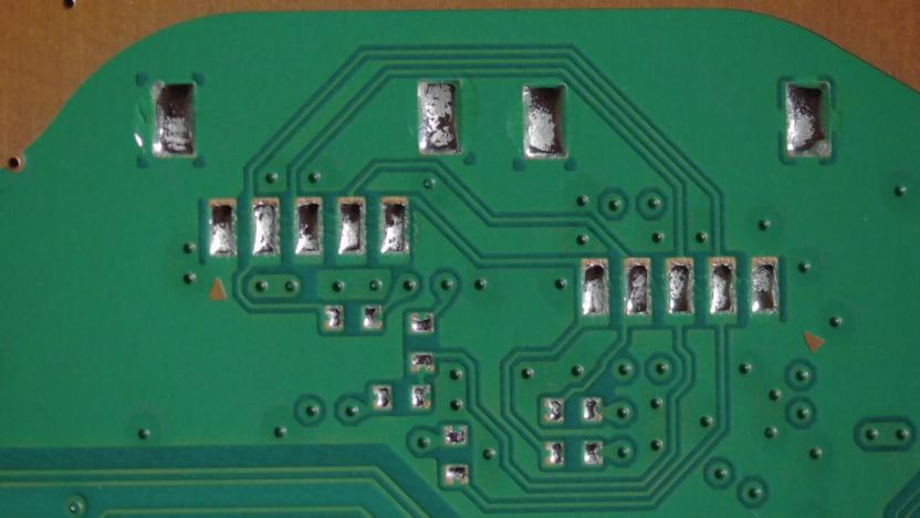
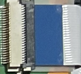
There are two Service Connectors on the PS5:
Pictures
First Connector (5 Pins)
Second Connector (24 Pins)
Meaning of Pins
- Starts at Leftmost (Indicated by Arrow)
5 Pins
| PIN | Meaning | Notes |
|---|---|---|
| GND | Ground | Ground Plane |
| TX EMC | Transmit EMC | Used to send commands to EMC. command always <com>:<chk>\r\n |
| RX EMC | Receive EMC | Used to recv responses from EMC. response always <res>:<chk>\r\n |
| ??? | ??? | ??? |
| ??? | ??? | ??? |
24 Pins
| PIN | Meaning | Notes |
|---|---|---|
| VDD | VDD | |
| VDD | VDD | |
| GND | GND | Ground Plane |
| GND | GND | Ground Plane |
| ??? | ??? | ??? |
| RX EMC | Receive EMC | Used to recv responses from EMC. response always <res>:<chk>\r\n |
| TX EMC | Transmit EMC | Used to send commands to EMC. command always <com>:<chk>\r\n |
| ??? | ??? | ??? |
| ??? | ??? | ??? |
| GND | GND | Ground Plane |
| ??? | ??? | ??? |
| ??? | ??? | ??? |
| ??? | ??? | ??? |
| ??? | ??? | ??? |
| GND | GND | Ground Plane |
| ??? | ??? | ??? |
| ??? | ??? | ??? |
| ??? | ??? | ??? |
| ??? | ??? | ??? |
| ??? | ??? | ??? |
| ??? | ??? | ??? |
| ??? | ??? | ??? |
| GND | GND | Ground Plane |
| ??? | ??? | ??? |

