Wireless communications: Difference between revisions
Jump to navigation
Jump to search
Physical Pin Layout:
Top
1 51
--------| |------------------
--------| |------------------
2 52
Bottom
Used pins:
Legend:
* = Connected
- = Not Connected
Top
1 51
********| |******************
*******-| |--**--***----*----
2 52
Bottom
Labled pins (Section incomplete):
Legend:
S = Signal Pin
P = Vcc or GND pin
U = Signal pin pulled up to Vcc
D = Signal pin pulled down to GND
- = Not Connected
Top
1 51
DSSDPSPS| |SSPSSSPSDDDDDDDDDS
PPPSSSS-| |--PP--SSP----P----
2 52
Bottom
Labled pinout:
Top:
1: WAKE#
3: Reserved (Wireless Coexistence Interface)
5: Reserved (Wireless Coexistence Interface)
7: CLKREQ#
9: GND
11: REFCLK-
13: REFCLK+
15: NC or GND
-
17: Reserved
19: Reserved
21: GND
23: PERn0
25: PERp0
27: GND
29: GND
31: PETn0
33: PETp0
35: GND
37: Reserved (Second PCIe lane. Tied to GND)
39: Reserved (Second PCIe lane. Tied to GND)
41: Reserved (Second PCIe lane. Tied to GND)
43: Reserved (Second PCIe lane. Tied to GND)
45: Reserved (Second PCIe lane. Tied to GND)
47: Reserved (Second PCIe lane. Tied to GND)
49: Reserved (Second PCIe lane. Tied to GND)
51: Reserved (W_DISABLE2#)
Bottom:
2: 3.3V
4: GND
6: 1.5V
8: VCC (SIM Card)
10: I/O (SIM Card)
12: CLK (SIM Card)
14: RST (SIM Card)
-
22: PERST#
24: +3.3Vaux
30: SMB_CLK
32: SMB_DATA
34: GND
44: LED_WLAN#
m (→Mobile Data Modem: cosmetic internal link) |
|||
| (75 intermediate revisions by 3 users not shown) | |||
| Line 1: | Line 1: | ||
[[Category:Hardware]]<noinclude>[[Category:Main]]</noinclude> | [[Category:Hardware]]<noinclude>[[Category:Main]]</noinclude> | ||
{| class="wikitable sortable" | |||
[[File:PSVita-wireless-card.jpg|400px|thumb|right|PSVITA PCH-1101 Wireless card]] | |||
[[File:Wireless-card-ZOE-MP-EMI-shields.jpg|300px|thumb|right|ZOE_MP wireless card with EMI shields]] | |||
[[File:ZOE_MP-Measurement.jpg|200px|thumb|right|ZOE_MP measurement]] | |||
[[File:ZOE_MP_wireless_card.jpg|200px|thumb|right|ZOE_MP wireless card]] | |||
[[File:Antenna-position.png|200px|thumb|right|Antenna Position (PCH-1100)]] | |||
[[File:Antenna.png|200px|thumb|right|Antenna Position (PCH-2000)]] | |||
== Wireless card == | |||
{| class="wikitable sortable" style="text-align: center;border:3px dotted #123AAA;" | |||
|- | |||
! colspan="5" | [[File:ZOE_MP-backside.jpg|300px|thumb|center|ZOE_MP wireless card backside]] | |||
|- | |- | ||
! Model !! Board !! | !! style="background-color:#ffffff; color:#123AAA;" |Model | ||
!! style="background-color:#ffffff; color:#123AAA;" |Board | |||
!! style="background-color:#ffffff; color:#123AAA;" |Modem | |||
!! style="background-color:#ffffff; color:#123AAA;" |SDRAM | |||
!! style="background-color:#ffffff; color:#123AAA;" |Antenna Switch Module | |||
|- | |- | ||
| PCH1101 || ZOE_MP || Qualcomm MDM6200 | | style="background-color:#ffffff; color:#123AAA;" |PCH1101 || style="background-color:#ffffff; color:#123AAA;" |ZOE_MP<br /> backside || <span style="background:red">[]</span> Qualcomm MDM6200 || <span style="background:orange">[]</span> Toshiba TY890A111222KA<br /> || <span style="background:yellow">[]</span> [http://www.sony.net/Products/SC-HP/new_pro/july_2010/pdf/cxm3555er_e.pdf Sony CXM3555ER] | ||
|- | |- | ||
| --- || --- || --- | | --- || --- || --- || --- || --- | ||
|- | |- | ||
|} | |} | ||
=== Bluetooth === | {| class="wikitable sortable" style="text-align: center;border:3px dotted #123AAA;" | ||
|- | |||
! colspan="9" | [[File:ZOE_MP.jpg|300px|thumb|center|ZOE_MP wireless card frontside]] | |||
|- | |||
!! style="background-color:#ffffff; color:#123AAA;" |Model | |||
!! style="background-color:#ffffff; color:#123AAA;" |Board | |||
!! style="background-color:#ffffff; color:#123AAA;" |Power Management | |||
!! style="background-color:#ffffff; color:#123AAA;" |Power Amplifier Module | |||
!! style="background-color:#ffffff; color:#123AAA;" |Power Amplifier Module | |||
!! style="background-color:#ffffff; color:#123AAA;" |Power Amplifier Module | |||
!! style="background-color:#ffffff; color:#123AAA;" |Power Amplifier Module | |||
!! style="background-color:#ffffff; color:#123AAA;" |Power Amplifier Module | |||
!! style="background-color:#ffffff; color:#123AAA;" |SAW Duplexer | |||
|- | |||
| style="background-color:#ffffff; color:#123AAA;" |PCH1101 || style="background-color:#ffffff; color:#123AAA;" |ZOE_MP<br /> front || <span style="background:red">[]</span> Qualcomm PM8028 || <span style="background:orange">[]</span> [http://www.avagotech.com/docs/AV02-2665EN Avago ACPM-7868]<br /> [http://en.wikipedia.org/wiki/GSM_frequency_bands GSM850/900 bands]<br /> DCS1800/PCS1900 bands || <span style="background:Aqua">[]</span> [http://www.avagotech.com/docs/AV02-2476EN Avago ACPM-5001]<br /> [http://en.wikipedia.org/wiki/UMTS_frequency_bands UMTS band: 1] <br />CDMA band: 6 || <span style="background:black">[]</span> [http://www.avagotech.com/docs/AV02-2480EN Avago ACPM-5008] <br />[http://en.wikipedia.org/wiki/UMTS_frequency_bands UMTS band: 8] || <span style="background:blue">[]</span> [http://www.avagotech.com/docs/AV02-2477EN Avago ACPM-5002] <br />[http://en.wikipedia.org/wiki/UMTS_frequency_bands UMTS band: 2] || <span style="background:purple">[]</span> [http://www.avagotech.com/docs/AV02-2479EN Avago ACPM-5005] <br />[http://en.wikipedia.org/wiki/UMTS_frequency_bands UMTS band: 5] <br />CDMA BC0 || <span style="background:yellow">[]</span> [http://en.tdk.eu/inf/40/ds/mc/B7964.pdf Epcos 7964] | |||
|- | |||
| --- || --- || --- || --- || --- || --- || --- || --- || --- | |||
|- | |||
|} | |||
On motherboard backside, there are a [http://www.marvell.com/wireless/avastar/88W8787/ Marvell 88W878S-BKB2 Avastar] WLAN/Bluetooth/FM Single-Chip SoC. | |||
Point Of Interest: On early manufactured [[SKU_Models|Stock Keeping Units]] (mostly with release firmware such as 1.06) there is a known issue with faulty 3G sub boards. For more information on how to remedy check the [[Error_Codes#C2|errors page]]: C2-9693-7. | |||
=== Gallery === | |||
<gallery> | |||
File:Playstation-vita-comm-front-web.jpg|ZOE_MP back (labelled as front by TECHINSIGHTS.com) | |||
File:Playstation-vita-comm-back-web.jpg|ZOE_MP front (labelled as back by TECHINSIGHTS.com) | |||
File:PM8028_HG11-VK495-200_diemrk.jpg|Qualcomm PM8028 die mark | |||
File:MDM6600_HG11-VF535-220_diemrk.jpg|Qualcomm MDM6600 die mark (same mark as MDM6200) | |||
</gallery> | |||
=== Mobile Data Modem === | |||
[https://www.qualcomm.com/documents/gobi-product-specs Qualcomm Gobi] is a family of embedded mobile broadband modem products by Qualcomm. One of the more notable products that contain a Gobi modem is the PSVita, which contains a MDM6200™ (note:the MDM6600 got closer specs than the MDM6270). | |||
{| class="wikitable" style="text-align: center;border:3px double #123AAA;" | |||
|- | |||
| style="background-color:#ffffff; color:#000000;" |'''Individual Chipsets''' | |||
| style="background-color:#ffffff; color:#000000;" |'''IMT-2000''' | |||
| style="background-color:#ffffff; color:#000000;" |'''Modem''' | |||
| style="background-color:#ffffff; color:#000000;" |'''Peak Data Rates''' | |||
| style="background-color:#ffffff; color:#000000;" |'''Application Processor''' | |||
| style="background-color:#ffffff; color:#000000;" |'''Voice''' | |||
| style="background-color:#ffffff; color:#000000;" |'''GPS''' | |||
| style="background-color:#ffffff; color:#000000;" |'''USB''' | |||
| style="background-color:#ffffff; color:#000000;" |'''Wifi''' | |||
|- | |||
| MDM6200 || 3G || HSPA+, GSM/GPRS/EDGE || Up to 14Mbps || {{No}} || {{Yes}} || gpsOneGen 8 with GLONASS|| USB 2.0 HS Peripheral or Host|| Supported with External Wifi | |||
|- | |||
The communication of the Modem appears to be PCIe, instead of the more common (Used on WWAN modems for laptops.) USB interface. So, the Vita might have PCIe available for use along with USB. In case anyone wants to try putting a mPCIe SSD in it or even hook up an external GPU to the Vita. | |||
</br> | |||
Physical Pin Layout:</br> | |||
Top</br> | |||
1 51</br> | |||
--------| |------------------</br> | |||
--------| |------------------</br> | |||
2 52</br> | |||
Bottom</br> | |||
</br> | |||
</br> | |||
Used pins:</br> | |||
Legend:</br> | |||
* = Connected</br> | |||
- = Not Connected</br> | |||
</br> | |||
Top</br> | |||
1 51</br> | |||
********| |******************</br> | |||
*******-| |--**--***----*----</br> | |||
2 52</br> | |||
Bottom</br> | |||
</br> | |||
</br> | |||
Labled pins (Section incomplete):</br> | |||
Legend:</br> | |||
S = Signal Pin</br> | |||
P = Vcc or GND pin</br> | |||
U = Signal pin pulled up to Vcc</br> | |||
D = Signal pin pulled down to GND</br> | |||
- = Not Connected</br> | |||
</br> | |||
Top</br> | |||
1 51</br> | |||
DSSDPSPS| |SSPSSSPSDDDDDDDDDS</br> | |||
PPPSSSS-| |--PP--SSP----P----</br> | |||
2 52</br> | |||
Bottom</br> | |||
</br> | |||
</br> | |||
Labled pinout:</br> | |||
Top:</br> | |||
1: WAKE#</br> | |||
3: Reserved (Wireless Coexistence Interface)</br> | |||
5: Reserved (Wireless Coexistence Interface)</br> | |||
7: CLKREQ#</br> | |||
9: GND</br> | |||
11: REFCLK-</br> | |||
13: REFCLK+</br> | |||
15: NC or GND</br> | |||
-</br> | |||
17: Reserved</br> | |||
19: Reserved</br> | |||
21: GND</br> | |||
23: PERn0</br> | |||
25: PERp0</br> | |||
27: GND</br> | |||
29: GND</br> | |||
31: PETn0</br> | |||
33: PETp0</br> | |||
35: GND</br> | |||
37: Reserved (Second PCIe lane. Tied to GND)</br> | |||
39: Reserved (Second PCIe lane. Tied to GND)</br> | |||
41: Reserved (Second PCIe lane. Tied to GND)</br> | |||
43: Reserved (Second PCIe lane. Tied to GND)</br> | |||
45: Reserved (Second PCIe lane. Tied to GND)</br> | |||
47: Reserved (Second PCIe lane. Tied to GND)</br> | |||
49: Reserved (Second PCIe lane. Tied to GND)</br> | |||
51: Reserved (W_DISABLE2#)</br> | |||
</br> | |||
</br> | |||
Bottom:</br> | |||
2: 3.3V</br> | |||
4: GND</br> | |||
6: 1.5V</br> | |||
8: VCC (SIM Card)</br> | |||
10: I/O (SIM Card)</br> | |||
12: CLK (SIM Card)</br> | |||
14: RST (SIM Card)</br> | |||
-</br> | |||
22: PERST#</br> | |||
24: +3.3Vaux</br> | |||
30: SMB_CLK</br> | |||
32: SMB_DATA</br> | |||
34: GND</br> | |||
44: LED_WLAN#</br> | |||
</code> | |||
|} | |||
=== | === Related articles === | ||
*[[Components]] (Parent Component is Half Mini PCIe Module) | |||
== [[File:Bluetooth.png|10px]] Bluetooth == | |||
* | *[[Bluetooth]] | ||
== GPS == | |||
== [[File:WiFi.png|20px]] WiFi == | |||
Module based on Marvell SD8787. | |||
Firmware in wlanbt_robin_img_ax.skprx starting at offset 305. | |||
Latest revision as of 15:17, 6 December 2022
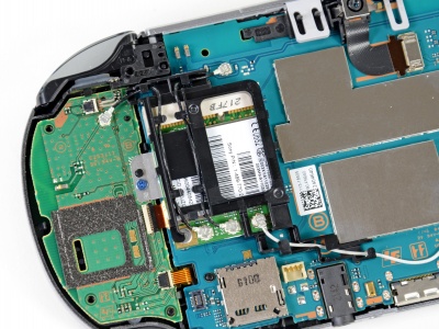
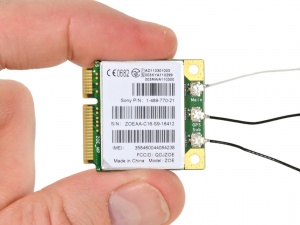
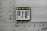
Wireless card[edit | edit source]
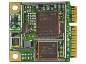
| Model | Board | Modem | SDRAM | Antenna Switch Module |
|---|---|---|---|---|
| PCH1101 | ZOE_MP backside |
[] Qualcomm MDM6200 | [] Toshiba TY890A111222KA |
[] Sony CXM3555ER |
| --- | --- | --- | --- | --- |
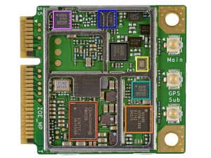
| Model | Board | Power Management | Power Amplifier Module | Power Amplifier Module | Power Amplifier Module | Power Amplifier Module | Power Amplifier Module | SAW Duplexer |
|---|---|---|---|---|---|---|---|---|
| PCH1101 | ZOE_MP front |
[] Qualcomm PM8028 | [] Avago ACPM-7868 GSM850/900 bands DCS1800/PCS1900 bands |
[] Avago ACPM-5001 UMTS band: 1 CDMA band: 6 |
[] Avago ACPM-5008 UMTS band: 8 |
[] Avago ACPM-5002 UMTS band: 2 |
[] Avago ACPM-5005 UMTS band: 5 CDMA BC0 |
[] Epcos 7964 |
| --- | --- | --- | --- | --- | --- | --- | --- | --- |
On motherboard backside, there are a Marvell 88W878S-BKB2 Avastar WLAN/Bluetooth/FM Single-Chip SoC.
Point Of Interest: On early manufactured Stock Keeping Units (mostly with release firmware such as 1.06) there is a known issue with faulty 3G sub boards. For more information on how to remedy check the errors page: C2-9693-7.
Gallery[edit | edit source]
Mobile Data Modem[edit | edit source]
Qualcomm Gobi is a family of embedded mobile broadband modem products by Qualcomm. One of the more notable products that contain a Gobi modem is the PSVita, which contains a MDM6200™ (note:the MDM6600 got closer specs than the MDM6270).
The communication of the Modem appears to be PCIe, instead of the more common (Used on WWAN modems for laptops.) USB interface. So, the Vita might have PCIe available for use along with USB. In case anyone wants to try putting a mPCIe SSD in it or even hook up an external GPU to the Vita.Physical Pin Layout:
Top
1 51
--------| |------------------
--------| |------------------
2 52
Bottom
Used pins:
Legend:
* = Connected
- = Not Connected
Top
1 51
********| |******************
*******-| |--**--***----*----
2 52
Bottom
Labled pins (Section incomplete):
Legend:
S = Signal Pin
P = Vcc or GND pin
U = Signal pin pulled up to Vcc
D = Signal pin pulled down to GND
- = Not Connected
Top
1 51
DSSDPSPS| |SSPSSSPSDDDDDDDDDS
PPPSSSS-| |--PP--SSP----P----
2 52
Bottom
Labled pinout:
Top:
1: WAKE#
3: Reserved (Wireless Coexistence Interface)
5: Reserved (Wireless Coexistence Interface)
7: CLKREQ#
9: GND
11: REFCLK-
13: REFCLK+
15: NC or GND
-
17: Reserved
19: Reserved
21: GND
23: PERn0
25: PERp0
27: GND
29: GND
31: PETn0
33: PETp0
35: GND
37: Reserved (Second PCIe lane. Tied to GND)
39: Reserved (Second PCIe lane. Tied to GND)
41: Reserved (Second PCIe lane. Tied to GND)
43: Reserved (Second PCIe lane. Tied to GND)
45: Reserved (Second PCIe lane. Tied to GND)
47: Reserved (Second PCIe lane. Tied to GND)
49: Reserved (Second PCIe lane. Tied to GND)
51: Reserved (W_DISABLE2#)
Bottom:
2: 3.3V
4: GND
6: 1.5V
8: VCC (SIM Card)
10: I/O (SIM Card)
12: CLK (SIM Card)
14: RST (SIM Card)
-
22: PERST#
24: +3.3Vaux
30: SMB_CLK
32: SMB_DATA
34: GND
44: LED_WLAN#
| Individual Chipsets | IMT-2000 | Modem | Peak Data Rates | Application Processor | Voice | GPS | USB | Wifi |
| MDM6200 | 3G | HSPA+, GSM/GPRS/EDGE | Up to 14Mbps | No | Yes | gpsOneGen 8 with GLONASS | USB 2.0 HS Peripheral or Host | Supported with External Wifi |
Related articles[edit | edit source]
- Components (Parent Component is Half Mini PCIe Module)
 Bluetooth[edit | edit source]
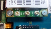
GPS[edit | edit source]
 WiFi[edit | edit source]
Module based on Marvell SD8787. Firmware in wlanbt_robin_img_ax.skprx starting at offset 305.
