Switch boards: Difference between revisions
m (→HSW-001) |
(added all leds to the board-model table) |
||
| Line 4: | Line 4: | ||
{| class="wikitable" | {| class="wikitable" | ||
|- | |- | ||
! rowspan="2" | PS3 Series !! colspan="2" | Power Eject board !! rowspan="2" | Connector<BR />(number of pins) !! colspan="2" | Buttons || colspan="4" | Leds | ! rowspan="2" | PS3 Series !! colspan="2" | Power Eject board !! rowspan="2" | Connector<BR />(number of pins) !! colspan="2" | Buttons || colspan="4" | Leds | ||
|- | |- | ||
! Model !! Part Nº !! Power !! Eject !! Power On !! | ! Model !! Part Nº !! Power !! Eject !! Power On/Standby/YLOD<BR />(1x dual green/red) !! Eject<BR />(1x blue) !! Power Eject backlight<BR />(4x white) !! Contour backlight<BR />(4x varies) | ||
|- | |- | ||
| 1000 Series | | 1000 Series | ||
| [[CSW-001]] || 1-871-871-21 || 10 || {{yes}} || {{yes}} || {{yes}} || {{yes}} || {{ | | [[CSW-001]] || 1-871-871-21 || 10 || {{yes}} || {{yes}} || {{yes}} || {{yes}} || {{no}} || {{no}} | ||
|- | |- | ||
| rowspan="2" | 2000 Series | | rowspan="2" | 2000 Series | ||
| [[DSW-001]] || 1-880-056-11 || 10 || {{yes}} || {{yes}} || {{yes}} || {{yes}} || {{yes}} || | | [[DSW-001]] || 1-880-056-11 || 10 || {{yes}} || {{yes}} || {{yes}} || {{yes}} || {{yes}} || {{yes}} | ||
|- | |- | ||
| [[HSW-001]] || 1-881-946-21 || 10 || {{yes}} || {{yes}} || {{yes}} || {{yes}} || {{yes}} || | | [[HSW-001]] || 1-881-946-21 || 10 || {{yes}} || {{yes}} || {{yes}} || {{yes}} || {{yes}} || {{yes}} | ||
|- | |- | ||
| 3000 Series | | 3000 Series | ||
| [[KSW-001]] || 1-884-751-31 || 6 || {{yes}} || {{yes}} || {{yes}} || {{no}} || {{no}} || | | [[KSW-001]] || 1-884-751-31 || 6 || {{yes}} || {{yes}} || {{yes}} || {{no}} || {{no}} || {{no}} | ||
|- | |- | ||
| 4000 Series | | 4000 Series | ||
| [[MSW-001]] || 1-886-929-11 || 6 || {{yes}} || {{no}} || {{yes}} || {{no}} || {{no}} || | | [[MSW-001]] || 1-886-929-11 || 6 || {{yes}} || {{no}} || {{yes}} || {{no}} || {{no}} || {{no}} | ||
|- | |- | ||
|} | |} | ||
*Notes | |||
**Boardmodel naming seems thus first letter of SKU motherboard (C=COK / D=DYN / K-KTE / M=MSX/MPX) + "SW-001" (with some exception, like the HSW-001 seen above) | |||
== CSW-001 == | == CSW-001 == | ||
| Line 135: | Line 137: | ||
To re-enable them is not only needed to populate the missing components, is also needed to be sure syscon is sending the correct signal to controll them (we have no idea when are supposed to be lighted). The components missing are easy to identificate because are the same than the others present at his side | To re-enable them is not only needed to populate the missing components, is also needed to be sure syscon is sending the correct signal to controll them (we have no idea when are supposed to be lighted). The components missing are easy to identificate because are the same than the others present at his side | ||
{{Boxframe0|content='''Other modding manuals related''' | |||
There is a manual to "bridge" the traces that goes to this "mysterious" leds with the "standby" or "eject" led in this link http://translate.google.com/translate?sl=fr&tl=en&js=n&prev=_t&hl=es&ie=UTF-8&u=http%3A%2F%2Fps3gunz.org%2Fforum%2Fviewtopic.php%3Fpid%3D590435&act=url | There is a manual to "bridge" the traces that goes to this "mysterious" leds with the "standby" or "eject" led in this link http://translate.google.com/translate?sl=fr&tl=en&js=n&prev=_t&hl=es&ie=UTF-8&u=http%3A%2F%2Fps3gunz.org%2Fforum%2Fviewtopic.php%3Fpid%3D590435&act=url | ||
*Notes | *Notes | ||
| Line 141: | Line 143: | ||
**He didnt taked care of the "bouncing surface" over the square (barelly visible in the photos) and along the curve... all the "light reactive" surface needs to be covered with a "mirror" sticker to make the light rays to "bounce" first in paralell direction to the surface, and then bounce again along the curve. This sticker doesnt exists (because they decided to disable all this), but for sure it was in the initial design to preserve the lighting | **He didnt taked care of the "bouncing surface" over the square (barelly visible in the photos) and along the curve... all the "light reactive" surface needs to be covered with a "mirror" sticker to make the light rays to "bounce" first in paralell direction to the surface, and then bounce again along the curve. This sticker doesnt exists (because they decided to disable all this), but for sure it was in the initial design to preserve the lighting | ||
Contour leds tests video: http://www.youtube.com/watch?v=leapBkrm5tk | |||
}} | |||
{{Console}} | {{Console}} | ||
[[Category:Power Eject boards]] | [[Category:Power Eject boards]] | ||
Revision as of 02:06, 3 July 2013
Power Eject boards
| PS3 Series | Power Eject board | Connector (number of pins) |
Buttons | Leds | |||||
|---|---|---|---|---|---|---|---|---|---|
| Model | Part Nº | Power | Eject | Power On/Standby/YLOD (1x dual green/red) |
Eject (1x blue) |
Power Eject backlight (4x white) |
Contour backlight (4x varies) | ||
| 1000 Series | CSW-001 | 1-871-871-21 | 10 | Yes | Yes | Yes | Yes | No | No |
| 2000 Series | DSW-001 | 1-880-056-11 | 10 | Yes | Yes | Yes | Yes | Yes | Yes |
| HSW-001 | 1-881-946-21 | 10 | Yes | Yes | Yes | Yes | Yes | Yes | |
| 3000 Series | KSW-001 | 1-884-751-31 | 6 | Yes | Yes | Yes | No | No | No |
| 4000 Series | MSW-001 | 1-886-929-11 | 6 | Yes | No | Yes | No | No | No |
- Notes
- Boardmodel naming seems thus first letter of SKU motherboard (C=COK / D=DYN / K-KTE / M=MSX/MPX) + "SW-001" (with some exception, like the HSW-001 seen above)
CSW-001
Power Eject board CSW-001 (PCB top view)
Power Eject board CSW-001 (PCB bottom view)
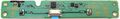
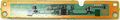
DSW-001
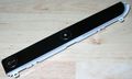
Power Eject board DSW-001 (top view)
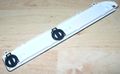
Power Eject board DSW-001 (bottom view)
Power Eject board DSW-001 (PCB top view)
Power Eject board DSW-001 (PCB bottom view)
.jpg)
.jpg)
.jpg)
.jpg)
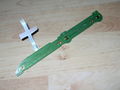
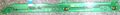
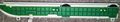
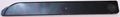
HSW-001
Power Eject board HSW-001 (top view)
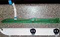
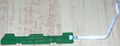
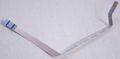
Power Eject board HSW-001 (PCB with ribbon cable, top view)
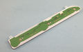
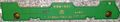
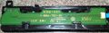
Power Eject board HSW-001 (PCB top view)
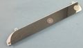
Power Eject board HSW-001 (PCB bottom view)
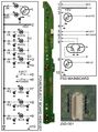
Power Eject board HSW-001 (JSD-001) schematic
.jpg)
.jpg)
_schematic.jpg)
| Pin | Signal/Connected to | Description | |
|---|---|---|---|
| On Motherboard | On Power Eject board | ||
| 1 | N.C. | 4x CONTOUR LEDs | Not connected on motherboard On Power Eject board it is sourced to 2 LEDs via T1 transistor and currentlimitor resistors of 3K and 820 Ω Two of these LEDs are missing on the Power Eject board, see modding section |
| 2 | VCC | VCC | +5V DC VCC |
| 3 | 4x WHITE LEDs | Inner light for power and eject buttons, each LED with a currentlimitor resistor of 1K Ω | |
| 4 | GND | GND | Ground |
| 5 | EJECT button | Sink to ground to activate | |
| 6 | POWER button | Sink to ground to activate | |
| 7 | RED led | Connects to red pin of dual red/green LED over power button, with a currentlimitor resistor of 1K2 Ω | |
| 8 | GREEN led | Connects to green pin of dual red/green LED over power button, with a currentlimitor resistor of 1K2 Ω | |
| 9 | BLUE led | Connects to blue LED over eject button, with a currentlimitor resistor of 560 Ω | |
| 10 | GND | GND | Ground |
KSW-001
Power Eject board KSW-001 (top view)
Power Eject board KSW-001 (PCB top view)
Power Eject board KSW-001 (PCB with ribbon cable, bottom view)
Power Eject board KSW-001 (PCB bottom view)
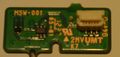
MSW-001
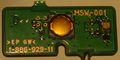
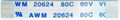
Power Eject board MSW-001 (PCB top view)
Power Eject board MSW-001 (PCB bottom view)
.jpg)
.jpg)
Flex Ribbon cables
PS3 1000 Series
Power Eject Flex Ribbon Cable (PS3 1000 series, top view)
Power Eject Flex Ribbon Cable (PS3 1000 series, bottom view)
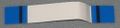
PS3 2000 Series
Power Eject Flex Ribbon Cable (PS3 2000 series, top view)
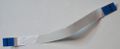
PS3 3000 Series
Power Eject Flex Ribbon Cable (PS3 3000 series, top view)
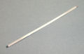
Power Eject Flex Ribbon Cable (PS3 3000 series, bottom view)
.jpg)
.jpg)
PS3 4000 Series
Modding
Enabling the "contour leds" in DSW-001 and HSW-001 power eject boards
.jpg)
PS3 2000 series (CECH-20xx, CECH-21xx, and CECH-25xx, with power eject boards DSW-001 and HSW-001) has been designed to have a lighted line all around the top edge of the power eject board
This is clearly visible in the plastic "light reactive" material used in the edge, and the square hole in the corner that allows the light to "transpass" the surface (with a 45 degrees angle bouncing surface at top of the hole that aligns the light rays in paralell to the buttons surface)
Under this square there are 2 leds (placed in opposite directions and diferent type, and another 2 missing leds at this side for a total of 4 leds) that are connected to a group of capacitors, resistors, and transistors (most of them not populated) and to the ribbon cable (that goes to syscon)
Why is this subcircuit present in this power eject boards is a mystery, obviously it was designed to be lighted but at some point somebody declined the idea (maybe poor lighting, maybe too scandalous for sony taste, who knows)... the point is the components are missing, so this leds at the corner are disabled from factory
To re-enable them is not only needed to populate the missing components, is also needed to be sure syscon is sending the correct signal to controll them (we have no idea when are supposed to be lighted). The components missing are easy to identificate because are the same than the others present at his side
There is a manual to "bridge" the traces that goes to this "mysterious" leds with the "standby" or "eject" led in this link http://translate.google.com/translate?sl=fr&tl=en&js=n&prev=_t&hl=es&ie=UTF-8&u=http%3A%2F%2Fps3gunz.org%2Fforum%2Fviewtopic.php%3Fpid%3D590435&act=url
- Notes
- this mod is not recommended, because the "bridged" line is taking too much current from the new leds, because doesnt even explain what is each line, because the leds are not controlled by syscon as originally was designed
- He didnt taked care of the "bouncing surface" over the square (barelly visible in the photos) and along the curve... all the "light reactive" surface needs to be covered with a "mirror" sticker to make the light rays to "bounce" first in paralell direction to the surface, and then bounce again along the curve. This sticker doesnt exists (because they decided to disable all this), but for sure it was in the initial design to preserve the lighting