Switch boards: Difference between revisions
m (→HSW-001: more notes) |
(cleanup/updated some sections) |
||
| Line 1: | Line 1: | ||
= | = Comparison of functionality = | ||
{| class="wikitable" | {| class="wikitable" | ||
| Line 31: | Line 31: | ||
*Notes | *Notes | ||
**Boardmodel naming seems thus first letter of SKU motherboard (C=COK / D=DYN / K-KTE / M=MSX/MPX) + "SW-001" (with some exception, like the HSW-001 seen above) | **Boardmodel naming seems thus first letter of SKU motherboard (C=COK / D=DYN / K-KTE / M=MSX/MPX) + "SW-001" (with some exception, like the HSW-001 seen above) | ||
= Power Eject boards Models = | |||
== CSW-001 == | == CSW-001 == | ||
| Line 65: | Line 67: | ||
! On Motherboard<!--// <BR />(Syscon [[SW2-30x]] pins) //--> !! On Power Eject board | ! On Motherboard<!--// <BR />(Syscon [[SW2-30x]] pins) //--> !! On Power Eject board | ||
|- | |- | ||
| 1 || style="color:white; background-color:darkgrey;" | N.C. || 4x CONTOUR LEDs || Not connected on motherboard<br />On Power Eject board is connected to a transistor driving 2 LEDs with currentlimitor resistors of 3K {{ohm}} (red led at left-top) and 820 {{ohm}} (blue led at left-bottom) | | 1 || style="color:white; background-color:darkgrey;" | N.C. || 4x CONTOUR LEDs || Not connected on motherboard<br />On Power Eject board is connected to a transistor driving 2 LEDs with currentlimitor resistors of 3K {{ohm}} (red led at left-top) and 820 {{ohm}} (blue led at left-bottom) | ||
|- | |- | ||
| 2 || style="color:white; background-color:#CC3333;" | VCC || style="color:white; background-color:#CC3333;" | VCC || style="color:white; background-color:#CC3333;" | +5V DC VCC | | 2 || style="color:white; background-color:#CC3333;" | VCC || style="color:white; background-color:#CC3333;" | VCC || style="color:white; background-color:#CC3333;" | +5V DC VCC | ||
| Line 86: | Line 88: | ||
|- | |- | ||
|} | |} | ||
*Notes | |||
**All LEDs on the board (except the subcircuit with the contour LEDs) are switched on/of from his GND pin (the other pin of the LED's is connected permanently to a volts line). In other words, when the LED is activated the line along the flex cable is connected to GND | |||
**Contour LED's | |||
***Are separated from the rest of the board by a transistor, the transistor is activated by a volts signal from PIN1 of the connector, but the motherboard doesnt send this signal, discuss in [[Talk:Power_Eject_boards|Talk Page]] | |||
***There are several ways to re-enable the contour LED's. And there are solder points without components to duplicate this subcircuit to add another 2 LEDs more for a total of 4. See [[Power_Eject_boards#Modding|Modding section]] | |||
== KSW-001 == | == KSW-001 == | ||
| Line 104: | Line 112: | ||
= Flex Ribbon cables = | = Flex Ribbon cables = | ||
<gallery> | <gallery> | ||
File:Power Eject Flex Ribbon Cable (PS3 1000 series, top view).jpg|Power Eject Flex Ribbon Cable (PS3 1000 series, top view) | File:Power Eject Flex Ribbon Cable (PS3 1000 series, top view).jpg|Power Eject Flex Ribbon Cable (PS3 1000 series, top view) | ||
File:Power Eject Flex Ribbon Cable (PS3 1000 series, bottom view).jpg|Power Eject Flex Ribbon Cable (PS3 1000 series, bottom view) | File:Power Eject Flex Ribbon Cable (PS3 1000 series, bottom view).jpg|Power Eject Flex Ribbon Cable (PS3 1000 series, bottom view) | ||
File:Power Eject Flex Ribbon Cable (PS3 2000 series, top view).jpg|Power Eject Flex Ribbon Cable (PS3 2000 series, top view) | |||
File:Power Eject Flex Ribbon Cable (PS3 3000 series, top view).jpg|Power Eject Flex Ribbon Cable (PS3 3000 series, top view) | |||
File:Power Eject Flex Ribbon Cable (PS3 3000 series, bottom view).jpg|Power Eject Flex Ribbon Cable (PS3 3000 series, bottom view) | |||
</gallery> | </gallery> | ||
== PS3 2000 | = Modding = | ||
== Contour backlight in DSW-001 and HSW-001 boards == | |||
PS3 2000 series ([[CECH-20xx]], [[CECH-21xx]], and [[CECH-25xx]], with power eject boards DSW-001 and HSW-001) has been designed to have a lighted line all around the top edge of the power eject board | |||
'''Light rays bouncing surfaces, and light reactive materials''' | |||
The plastic plate uses a "light reactive" material along the edge and in a squared hole in the corner allows the light to "transpass" it | |||
The ligth rays "bounces" inside this material, and the first bouncing surface over the squared hole is a plane at 45 degrees angle. This first bounce aligns the light rays in paralell to the board, the next bounces happens all along the curved surface in horizontal | |||
The reflection of this surfaces can be increased a bit with chrome stickers (or alluminium tape). The case has a plane border of 3,5mm x 17,7mm perfect to stick in it, this way the glue layer of the sticker is at the other side, but the case doesnt have the 45 degrees surface (it has a weird hole instead), you can use other colors for the sticker/s because the color is partially visible from outside (preferably lighter colors or one that matches your led/s color to enhance it) | |||
<gallery> | <gallery> | ||
File:Power Eject | File:Power Eject board PS3 2000 series (light rays schematic in contour leds).jpg|Power Eject board PS3 2000 series<BR />Light rays schematic in contour leds | ||
File:Power Eject board DSW-001 (bottom view).jpg|Power Eject board PS3 2000 series<BR />Detail of the transparent "light reactive" square hole in the corner | |||
</gallery> | </gallery> | ||
'''Contour LEDs subcircuit''' | |||
In HSW-001 board there are 2 leds connected to 2 resistors, 1 zener diode, and 1 transistor (and unpopulated solder points for another similar group of components) all this subcircuit is driven from PIN1 line in the connector | |||
Why is this subcircuit present in this power eject boards is a mystery, obviously it was designed to be lighted but at some point somebody declined the idea (maybe poor lighting, maybe too scandalous for sony taste, who knows)... the point is the the line is cutted in the motherboard, and half of the components are missing so this contour backlight is disabled from factory | |||
The subcircuit is activated by the transistor base pin that goes in-line with the other unpopulated transistor base pin, both does the same function at the same time, each transistor is in chargue of 2 leds with a common zenner diode (the transistor opens/closes the leds ground lines, and when the line is opened the zener diode works as an "voltage regulator" for the subcircuit avoiding "voltage peaks"). These transistors are "isolating" the subcircuit at his left | |||
The unpopulated resistors values are dependant of the leds added | |||
<gallery> | <gallery> | ||
File:Power Eject | File:Power Eject board HSW-001 (PCB top view).jpg|Power Eject board HSW-001<BR />PCB top view | ||
File:Power Eject | File:Power Eject board HSW-001 (Contour LEDs subcircuit, unpopulated components).jpg|Power Eject board HSW-001<BR />Contour LEDs subcircuit, unpopulated components | ||
</gallery> | </gallery> | ||
== | === Contour backlight enabled bypassing the transistor === | ||
With this method, all the ground pins of the background light LED's are joined together and switched at the same time (4 white LED's from power/eject buttons + the LEDs present in the "contour backlight" subcircuit) | |||
The wire is bridging the connector PIN3 (that switches on/of the backlight for power eject buttons) to the collector pin of the transistor, but also is connected to the collector pin of the other unpopulated transistor, this means all the 4 LEDs of the subcircuit will be activated at the same time by the wire (in the case of adding the 2 missing LEDs with this 2 resistors), and has a common zenner diode to protect the 4 LEDs lines lines from voltage peaks | |||
The transistor function is bypassed by this wire so the area at the left of the transistor/s is not an isolated subcircuit anymore, this can be a problem for the total current of the board and for this reason in the photo there is an "optional" cutted line to disable the white leds for power eject buttons (you are adding 4 leds, so other 4 "needs" to be disabled to ballance the karma) | |||
In the case the transistor is activated (seems not posible because the trace is cutted in motherboard) the collector pin (ground for leds) is connected to the the emitter pin (common ground of the board), this doesnt interferes with the added wire because is doing the same function | |||
The top-left LED (red) ground is connected to this tiny black component in verticall that is a '''HUGE''' resistor of 3K {{ohm}}, the value of the resistor makes the red light almost not visible, so is a good idea to remove either the resistor or the red LED, is also a good idea to remove one or more LEDs because are different colors (better use one colored LED + 3 whites... or 4 of the same color) | |||
To remove a resistor so tiny with a solder iron there is a trick using a melted drop that connects both pins of the component and when all is melted you move the component laterally. If you approach a solder iron to a LED of this size his plastic cover will "pop up" in 100% of the cases, if you dont plan to recycle the LED this is not a problem, first you destroy/popup the plastic cover of the LED with the solder tip and then you can use the trick of the melted solder drop, the only caution needed is to dont damage other nearly components and use a good solder iron with a 0,5mm tip or so | |||
<gallery> | |||
File:Power Eject board HSW-001 (Enabling contour LEDs, minimal parts version).jpg|Power Eject board HSW-001<BR />(Enabling contour LEDs, minimal parts version) | |||
</gallery> | |||
=== Other modding manuals related === | |||
There is a manual to "bridge" the traces that goes to this "mysterious" leds with the "standby" or "eject" led in this link http://translate.google.com/translate?sl=fr&tl=en&js=n&prev=_t&hl=es&ie=UTF-8&u=http%3A%2F%2Fps3gunz.org%2Fforum%2Fviewtopic.php%3Fpid%3D590435&act=url | There is a manual to "bridge" the traces that goes to this "mysterious" leds with the "standby" or "eject" led in this link http://translate.google.com/translate?sl=fr&tl=en&js=n&prev=_t&hl=es&ie=UTF-8&u=http%3A%2F%2Fps3gunz.org%2Fforum%2Fviewtopic.php%3Fpid%3D590435&act=url | ||
*Notes | *Notes | ||
| Line 150: | Line 178: | ||
Contour leds tests video: http://www.youtube.com/watch?v=leapBkrm5tk | Contour leds tests video: http://www.youtube.com/watch?v=leapBkrm5tk | ||
{{Console}} | {{Console}} | ||
[[Category:Power Eject boards]] | [[Category:Power Eject boards]] | ||
Revision as of 03:44, 5 July 2013
Comparison of functionality
| PS3 Series | Power Eject board | Connector (number of pins) |
Buttons | Leds | |||||
|---|---|---|---|---|---|---|---|---|---|
| Model | Part Nº | Power | Eject | Standby/Power On/YLOD | Eject | Power Eject buttons backlight | Board contour backlight | ||
| 1000 Series | CSW-001 | 1-871-871-21 | 10 | Yes | Yes | 1x red + 1x green | 1x blue | No | No |
| 2000 Series | DSW-001 | 1-880-056-11 | 10 | Yes | Yes | 1x red/green (dual) | 1x blue | 2x white (power) + 2x white (eject) | 1x red (left-top) + 1x blue (left-bottom) + 1x green (right-top) + 1 unpopulated |
| HSW-001 | 1-881-946-21 | 10 | Yes | Yes | 1x red/green (dual) | 1x blue | 2x white (power) + 2x white (eject) | 1x red (left-top) + 1x blue (left-bottom) + 2 unpopulated | |
| 3000 Series | KSW-001 | 1-884-751-31 | 6 | Yes | Yes | 1x red/green (dual) | No | No | No |
| 4000 Series | MSW-001 | 1-886-929-11 | 6 | Yes | No | 1x red/green (dual) | No | No | No |
- Notes
- Boardmodel naming seems thus first letter of SKU motherboard (C=COK / D=DYN / K-KTE / M=MSX/MPX) + "SW-001" (with some exception, like the HSW-001 seen above)
Power Eject boards Models
CSW-001
Power Eject board CSW-001 (PCB top view)
Power Eject board CSW-001 (PCB bottom view)
DSW-001
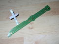
Power Eject board DSW-001 (top view)
Power Eject board DSW-001 (bottom view)
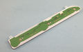
Power Eject board DSW-001 (PCB top view)
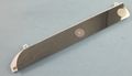
Power Eject board DSW-001 (PCB bottom view)
.jpg)
.jpg)
.jpg)
.jpg)
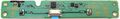
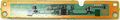
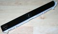
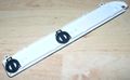
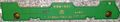
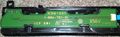
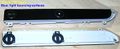
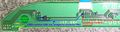
HSW-001
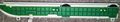
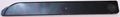
Power Eject board HSW-001 (top view)
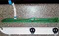
Power Eject board HSW-001 (PCB with ribbon cable, top view)

Power Eject board HSW-001 (PCB top view)
Power Eject board HSW-001 (PCB bottom view)
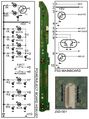
Power Eject board HSW-001 (JSD-001) schematic
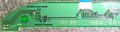
Power Eject board HSW-001 (Contour LEDs subcircuit, unpopulated components)
.jpg)
.jpg)
_schematic.jpg)
| Pin | Signal/Connected to | Description | |
|---|---|---|---|
| On Motherboard | On Power Eject board | ||
| 1 | N.C. | 4x CONTOUR LEDs | Not connected on motherboard On Power Eject board is connected to a transistor driving 2 LEDs with currentlimitor resistors of 3K Ω (red led at left-top) and 820 Ω (blue led at left-bottom) |
| 2 | VCC | VCC | +5V DC VCC |
| 3 | 4x WHITE LEDs | Inner light for power and eject buttons, power LEDs with a currentlimitor resistor of 1K Ω, and eject LEDs with a currentlimitor resistor of 910 Ω | |
| 4 | GND | GND | Ground |
| 5 | EJECT button | Sink to ground to activate | |
| 6 | POWER button | Sink to ground to activate | |
| 7 | GREEN led | Connects to left-bottom corner pin (green gnd) of dual red/green LED over power button, with a currentlimitor resistor of 1K Ω | |
| 8 | RED led | Connects to left-top corner pin (red gnd) of dual red/green LED over power button, with a currentlimitor resistor of 1K2 Ω | |
| 9 | BLUE led | Connects to blue LED over eject button, with a currentlimitor resistor of 560 Ω | |
| 10 | GND | GND | Ground |
- Notes
- All LEDs on the board (except the subcircuit with the contour LEDs) are switched on/of from his GND pin (the other pin of the LED's is connected permanently to a volts line). In other words, when the LED is activated the line along the flex cable is connected to GND
- Contour LED's
- Are separated from the rest of the board by a transistor, the transistor is activated by a volts signal from PIN1 of the connector, but the motherboard doesnt send this signal, discuss in Talk Page
- There are several ways to re-enable the contour LED's. And there are solder points without components to duplicate this subcircuit to add another 2 LEDs more for a total of 4. See Modding section
KSW-001
Power Eject board KSW-001 (top view)
Power Eject board KSW-001 (PCB top view)
Power Eject board KSW-001 (PCB with ribbon cable, bottom view)
Power Eject board KSW-001 (PCB bottom view)
MSW-001
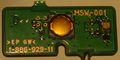
Power Eject board MSW-001 (PCB top view)
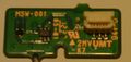
Power Eject board MSW-001 (PCB bottom view)
.jpg)
.jpg)
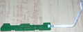
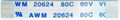
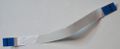
Flex Ribbon cables
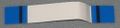
Power Eject Flex Ribbon Cable (PS3 1000 series, top view)
Power Eject Flex Ribbon Cable (PS3 1000 series, bottom view)
Power Eject Flex Ribbon Cable (PS3 2000 series, top view)
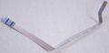
Power Eject Flex Ribbon Cable (PS3 3000 series, top view)
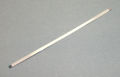
Power Eject Flex Ribbon Cable (PS3 3000 series, bottom view)
.jpg)
.jpg)
Modding
Contour backlight in DSW-001 and HSW-001 boards
PS3 2000 series (CECH-20xx, CECH-21xx, and CECH-25xx, with power eject boards DSW-001 and HSW-001) has been designed to have a lighted line all around the top edge of the power eject board
Light rays bouncing surfaces, and light reactive materials
The plastic plate uses a "light reactive" material along the edge and in a squared hole in the corner allows the light to "transpass" it
The ligth rays "bounces" inside this material, and the first bouncing surface over the squared hole is a plane at 45 degrees angle. This first bounce aligns the light rays in paralell to the board, the next bounces happens all along the curved surface in horizontal
The reflection of this surfaces can be increased a bit with chrome stickers (or alluminium tape). The case has a plane border of 3,5mm x 17,7mm perfect to stick in it, this way the glue layer of the sticker is at the other side, but the case doesnt have the 45 degrees surface (it has a weird hole instead), you can use other colors for the sticker/s because the color is partially visible from outside (preferably lighter colors or one that matches your led/s color to enhance it)
Power Eject board PS3 2000 series
Light rays schematic in contour ledsPower Eject board PS3 2000 series
Detail of the transparent "light reactive" square hole in the corner
Contour LEDs subcircuit
In HSW-001 board there are 2 leds connected to 2 resistors, 1 zener diode, and 1 transistor (and unpopulated solder points for another similar group of components) all this subcircuit is driven from PIN1 line in the connector
Why is this subcircuit present in this power eject boards is a mystery, obviously it was designed to be lighted but at some point somebody declined the idea (maybe poor lighting, maybe too scandalous for sony taste, who knows)... the point is the the line is cutted in the motherboard, and half of the components are missing so this contour backlight is disabled from factory
The subcircuit is activated by the transistor base pin that goes in-line with the other unpopulated transistor base pin, both does the same function at the same time, each transistor is in chargue of 2 leds with a common zenner diode (the transistor opens/closes the leds ground lines, and when the line is opened the zener diode works as an "voltage regulator" for the subcircuit avoiding "voltage peaks"). These transistors are "isolating" the subcircuit at his left
The unpopulated resistors values are dependant of the leds added
Power Eject board HSW-001
PCB top viewPower Eject board HSW-001
Contour LEDs subcircuit, unpopulated components
Contour backlight enabled bypassing the transistor
With this method, all the ground pins of the background light LED's are joined together and switched at the same time (4 white LED's from power/eject buttons + the LEDs present in the "contour backlight" subcircuit)
The wire is bridging the connector PIN3 (that switches on/of the backlight for power eject buttons) to the collector pin of the transistor, but also is connected to the collector pin of the other unpopulated transistor, this means all the 4 LEDs of the subcircuit will be activated at the same time by the wire (in the case of adding the 2 missing LEDs with this 2 resistors), and has a common zenner diode to protect the 4 LEDs lines lines from voltage peaks
The transistor function is bypassed by this wire so the area at the left of the transistor/s is not an isolated subcircuit anymore, this can be a problem for the total current of the board and for this reason in the photo there is an "optional" cutted line to disable the white leds for power eject buttons (you are adding 4 leds, so other 4 "needs" to be disabled to ballance the karma)
In the case the transistor is activated (seems not posible because the trace is cutted in motherboard) the collector pin (ground for leds) is connected to the the emitter pin (common ground of the board), this doesnt interferes with the added wire because is doing the same function
The top-left LED (red) ground is connected to this tiny black component in verticall that is a HUGE resistor of 3K Ω, the value of the resistor makes the red light almost not visible, so is a good idea to remove either the resistor or the red LED, is also a good idea to remove one or more LEDs because are different colors (better use one colored LED + 3 whites... or 4 of the same color)
To remove a resistor so tiny with a solder iron there is a trick using a melted drop that connects both pins of the component and when all is melted you move the component laterally. If you approach a solder iron to a LED of this size his plastic cover will "pop up" in 100% of the cases, if you dont plan to recycle the LED this is not a problem, first you destroy/popup the plastic cover of the LED with the solder tip and then you can use the trick of the melted solder drop, the only caution needed is to dont damage other nearly components and use a good solder iron with a 0,5mm tip or so
Power Eject board HSW-001
(Enabling contour LEDs, minimal parts version)
There is a manual to "bridge" the traces that goes to this "mysterious" leds with the "standby" or "eject" led in this link http://translate.google.com/translate?sl=fr&tl=en&js=n&prev=_t&hl=es&ie=UTF-8&u=http%3A%2F%2Fps3gunz.org%2Fforum%2Fviewtopic.php%3Fpid%3D590435&act=url
- Notes
- this mod is not recommended, because the "bridged" line is taking too much current from the new leds, because doesnt even explain what is each line, because the leds are not controlled by syscon as originally was designed
- He didnt taked care of the "bouncing surface" over the square (barelly visible in the photos) and along the curve... all the "light reactive" surface needs to be covered with a "mirror" sticker to make the light rays to "bounce" first in paralell direction to the surface, and then bounce again along the curve. This sticker doesnt exists (because they decided to disable all this), but for sure it was in the initial design to preserve the lighting
Contour leds tests video: http://www.youtube.com/watch?v=leapBkrm5tk