PlayStation 4 Camera: Difference between revisions
| Line 232: | Line 232: | ||
| 1 || bDescriptorType || 1 || 0x05 || (= 5) | | 1 || bDescriptorType || 1 || 0x05 || (= 5) | ||
|- | |- | ||
| 2 || bEndpointAddress || 1 || 0x01 || OUT ( | | 2 || bEndpointAddress || 1 || 0x01 || OUT<--(00 00 0001)-->1 | ||
<small> | <small> | ||
The address of this endpoint within the device: | The address of this endpoint within the device: | ||
| Line 284: | Line 284: | ||
| 1 || bDescriptorType || 1 || 0x05 || ( =5) | | 1 || bDescriptorType || 1 || 0x05 || ( =5) | ||
|- | |- | ||
| 2 || bEndpointAddress || 1 || 0x82 || IN ( | | 2 || bEndpointAddress || 1 || 0x82 || IN<--(10 00 0010)-->2 | ||
|- | |- | ||
| 3 || bmAttributes || 1 || 0x02 || Bulk | | 3 || bmAttributes || 1 || 0x02 || Bulk | ||
Revision as of 14:19, 4 February 2014
Playstation 4 Camera
Specifications
| Overview of Technical Specifications | |
|---|---|
| Product Code | CUH-ZEY1 |
| External Dimension | approximately 186mm x 27mm x 27mm (height x width x depth) |
| Weight | approximately 183g |
| Cable Length | Cord length: 200cm approximately |
| Connection Type | PS4 dedicated connector AUX (USB 3.0-derived) |
| Capture Range | 30cm - ∞ |
| Camera lens | Dual camera (move like) |
| Aperture | f/2.0 /fixed focus |
| Field of view (FOV) | 85° |
| Video Format | RAW16/RAW8, YUV422/YUV8 (greyscale) |
| Video Frame Rate |
|
| Color depth | 12-bit tonal gradation (=4096 tonal levels) |
| Microphone | 4 Channel Microphone Array |
| Programmable settings |
|
The PlayStation 4 Camera runs without user login (kernel/system device?) and depends for many of its system functions on the APU, using a tripple buffering system
Available functions:
- photo, video
- depth calculation/imaging
- pad, move, face, head and hand recognition/tracking
- one of the cameras can be used for generating the video image, with the other used for motion tracking.
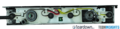
Back chip connected to Aux port is labeled OV00580-B21G-1C. The OmniVision 580 ASIC is not documented, so it seems it was made specially for Sony out of the 500/600 serie (none of them featuring USB 3.0, see external reference).
Front chip connected to microphone array is labeled 5703 324A.
Gallery
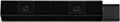
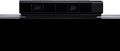
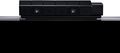
Pre E3 Playstation 4 Camera pictures

PS4 Camera - pic1
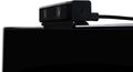
PS4 Camera - pic2
PS4 Camera - pic3
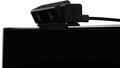
PS4 Camera - pic4
PS4 Camera - pic5
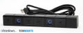
PS4 Camera - pic6
PS4 Camera - pic7
PS4 Camera - pic8


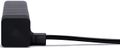
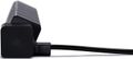
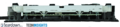
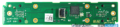
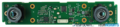
Playstation 4 Camera teardown pictures
PS4 Camera - picture 0
PS4 Camera - picture 1
PS4 Camera - picture 2
PS4 Camera - picture 3
PS4 Camera - picture 4
Videos
(The C-Note Files - Episode 12: Tutorial - PS4 Face Recognition)
(The C-Note Files - Episode 13: Tutorial - PS4 Voice Recognition)
Analysis
USB
Device Descriptor
| Device Descriptor | ||||
|---|---|---|---|---|
| Offset | Field | Size | Value | Description |
| 0 | bLength | 1 | 0x12 | Size of this descriptor in bytes (18) |
| 1 | bDescriptorType | 1 | 0x01 | DEVICE descriptor type (Constant = 1) |
| 2 | bcdUSB | 2 | 0x0300 | USB Spec release number (3.00):
with which the device and is descriptors are compliant (e.g.: 0x0200 (USB2.0), 0x0300, (USB3.0)) |
| 4 | bDeviceClass | 1 | 0x00 | Class code assigned by USB-IF
(used by the operating system to find a class driver for your device)
|
| 5 | bDeviceSubClass | 1 | 0x00 | SubClass Code assigned by USB-IF
(used by the operating system to find a class driver for your device) |
| 6 | bDeviceProtocol | 1 | 0x00 | Protocol Code assigned by USB-IF
(used by the operating system to find a class driver for your device) |
| 7 | bMaxPacketSize0 | 1 | 0x09 | Max packet size for endpoint 0.
|
| 8 | idVendor | 2 | 0x05a9 | Vendor ID (VID) (OmniVision Technologies, Inc.) - must be obtained from USB-IF
(used by the operating system to find a driver for your device) |
| 10 | idProduct | 2 | 0x0580 | Product ID (PID) - assigned by the manufacturer
(used by the operating system to find a driver for your device) |
| 12 | bcdDevice | 2 | 0x0100 | Device release number (Version: 1.00)
in binary coded decimal |
| 14 | iManufacturer | 1 | 0x01 | Index of string descriptor describing manufacturer
set to 0 if no string |
| 15 | iProduct | 1 | 0x02 | Index of string descriptor describing product
set to 0 if no string |
| 16 | iSerialNumber | 1 | 0x00 | Index of string descriptor describing device serial number set to 0 if no string |
| 17 | bNumConfigurations | 1 | 0x01 | Number of possible configurations |
Configuration Descriptor
| Configuration Descriptor | |||||||||||
|---|---|---|---|---|---|---|---|---|---|---|---|
| Offset | Field | Size | Value | Description | |||||||
| 0 | bLength | 1 | 0x09 | Size | |||||||
| 1 | bDescriptorType | 1 | 0x02 | (= 2) | |||||||
| 2 | wTotalLength | 2 | 0x002C | Total number of bytes (44) in this descriptor and all the following descriptors (9+9+ + +) | |||||||
| 4 | bNumInterfaces | 1 | 0x01 | Number of interfaces supported by this configuration | |||||||
| 5 | bConfigurationValue | 1 | 0x01 | Value used by Set Configuration to select this configuration | |||||||
| 6 | iConfiguration | 1 | 0x00 | Index of string descriptor describing configuration - set to 0 if no string | |||||||
| 7 | bmAttributes | 1 | 0x80 | Powered by the bus (10000000)
specify power parameters for the configuration :
| |||||||
| 8 | bMaxPower | 1 | 0x32 | Maximum current: 100mA drawn by device in this configuration. In units of 2mA. So 0x32 (50) means 100 mA | |||||||
| Interface Descriptor | |||||||||||
| 0 | bLength | 1 | 0x09 | Size | |||||||
| 1 | bDescriptorType | 1 | 0x04 | (= 4) | |||||||
| 2 | bInterfaceNumber | 1 | 0x00 | Number identifying this interface.
Zero-based value | |||||||
| 3 | bAlternateSetting | 1 | 0x00 | The first (and default) value used to select alternative setting is always 0
(An interface can have more than one variant, and these variants can be switched between, while other interfaces are still in operation) | |||||||
| 4 | bNumEndpoints | 1 | 0x02 | Number of Endpoints used for this interface | |||||||
| 5 | bInterfaceClass | 1 | 0xFF | Class code assigned by USB-IF
| |||||||
| 6 | bInterfaceSubClass | 1 | 0x00 | SubClass Code assigned by USB-IF | |||||||
| 7 | bInterfaceProtocol | 1 | 0x00 | Protocol Code assigned by USB-IF | |||||||
| 8 | iInterface | 1 | 0x00 | Index of string descriptor describing interface - set to 0 if no string | |||||||
| Endpoint (OUT) Descriptor | |||||||||||
| 0 | bLength | 1 | 0x0- | Size | |||||||
| 1 | bDescriptorType | 1 | 0x05 | (= 5) | |||||||
| 2 | bEndpointAddress | 1 | 0x01 | OUT<--(00 00 0001)-->1
The address of this endpoint within the device:
| |||||||
| 3 | bmAttributes | 1 | 0x02 | Bulk (00000010)
(D1:0) Transfer Type:
The following only apply to isochronous endpoints. Else set to 0. (D3:2) Synchronisation Type (ISO mode):
(D5:4) Usage Type (ISO mode):
(D7:6) Reserved Set to 0 | |||||||
| 4 | wMaxPacketSize | 2 | 0x0400 | (1024) | |||||||
| 6 | bInterval | 1 | 0x00 | - (unit depends on device speed)
Interval for polling endpoint for data transfers. Expressed in frames (ms) for low/full speed or microframes (125µs) for high speed | |||||||
| - | bMaxBurst | 1 | 0x0F | MaxBurst (15)
The number of packets the endpoint can send or receive as part of a burst (range 1 - 16). See transfer Type. | |||||||
| Endpoint (IN) Descriptor | |||||||||||
| 0 | bLength | 1 | 0x0- | Size | |||||||
| 1 | bDescriptorType | 1 | 0x05 | ( =5) | |||||||
| 2 | bEndpointAddress | 1 | 0x82 | IN<--(10 00 0010)-->2 | |||||||
| 3 | bmAttributes | 1 | 0x02 | Bulk | |||||||
| 4 | wMaxPacketSize | 2 | 0x0400 | (1024) | |||||||
| 6 | bInterval | 1 | 0x00 | 0 | |||||||
| - | bMaxBurst | 1 | 0x0F | MaxBurst (15) | |||||||
| Binary Object Store Descriptor | |||||||||||
| 0 | bLength | 1 | 0x05 | Size (05) | |||||||
| 1 | bDescriptorType | 1 | 0x0F | (= 15) | |||||||
| 2 | wTotalLength | 1 | 0x16 | (22) (5+7+10) | |||||||
| 3 | bNumDeviceCaps | 1 | 0x02 | (2)
must be at least 2 for SuperSpeed devices and equal to 3 for USB 3.0 hubs. | |||||||
| - | USB 2.0 Extension Device Capability: | ||||||||||
| bLength | 1 | 0x07 | (7) Size | ||||||||
| bDescriptorType | 1 | 0x10 | ( =16) | ||||||||
| bDevCapabilityType | 1 | 0x02 | (2)
| ||||||||
| bmAttributes | 4 | 0x00000002 | (00000000 00000000 00000000 00000010) Link Power Management supported
See USB2-LPM-Errata-final.pdf p3
| ||||||||
| - | SuperSpeed USB Device Capability: | ||||||||||
| bLength | 1 | 0x0A | (10) Size | ||||||||
| bDescriptorType | 1 | 0x10 | (= 16) | ||||||||
| bDevCapabilityType | 1 | 0x03 | (3) | ||||||||
| bmAttributes | 1 | 0x00 | (00000000)
| ||||||||
| wSpeedsSupported | 0x000e |
| |||||||||
| bFunctionalitySupport |
Lowest fully-functional device speed is Full Speed 12Mbps) | ||||||||||
| bU1DevExitLat | 10µ | ||||||||||
| bU2DevExitLat | 32µs | ||||||||||
| Device Status | 0x0000 | ||||||||||
External references
Generic
- http://en.wikipedia.org/wiki/Computer_stereo_vision
- Gesture recognition: Enabling natural interactions with electronic
- Softkinetic Patent:
Computer videogame system with body position detector
