HSW-001: Difference between revisions
(hmmm, so the HSW-001 was used also in CECH-21xx with SUR-001 motherboards... good to know this was a doubt i had (and still remains in some wiki pages) im going to fix it, thx kozarovv ;) |
(moved from Switch boards page) |
||
| Line 7: | Line 7: | ||
<gallery> | <gallery> | ||
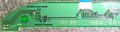
File:Power Eject board HSW-001 (top view).jpg|Switch board HSW-001 (top view) | |||
File:Power Eject board HSW-001 (PCB with ribbon cable, top view).jpg|Switch board HSW-001 (PCB with ribbon cable, top view) | |||
File:1-881-946-11.jpg|Switch board HSW-001, 1-881-946-11. Unknown manufacturer | File:1-881-946-11.jpg|Switch board HSW-001, 1-881-946-11. Unknown manufacturer | ||
File:Power Eject board HSW-001 (PCB top view).jpg|Switch board HSW-001 (PCB top view) | |||
File:Power Eject board HSW-001 (PCB bottom view).jpg|Switch board HSW-001 (PCB bottom view), 1-881-946-21. Produced by Foxconn | File:Power Eject board HSW-001 (PCB bottom view).jpg|Switch board HSW-001 (PCB bottom view), 1-881-946-21. Produced by Foxconn | ||
File:Power Eject board HSW-001 (JSD-001) schematic.jpg|Switch board HSW-001 (JSD-001) schematic | |||
File:Power Eject board HSW-001 (Contour LEDs subcircuit, unpopulated components).jpg|Switch board HSW-001 (Contour LEDs subcircuit, unpopulated components) | |||
File:SYSCON SWx JTP-001 JSD-001 HSW-001 CN101.jpg|PS3 Power control and switches schematic for CECH-25xx series<br>Motherboards JTP-001 or JSD-001, SYSCON SW-x series, Switch board HSW-001, and 4 pins PSU connector (CN101) for PSU models APS-270 or EADP-200DB | |||
</gallery> | </gallery> | ||
= Pinout = | = Pinout = | ||
{{HSW-001 pinout}} | {{HSW-001 pinout}} | ||
= How it works = | |||
All LED's on the switch board are turned on/off either by syscon or by the BD drive by using an intermediary transistor that drives the LED ground pin (and the other pin of the LED's is connected permanently to the 5 volts standby line present in the switch board at all times). All LED's have its own resistor with a different value to control the current (thus light intensity) and one or more diodes to protect the circuit | |||
When Power and/or Eject switches are pressed the correlating syscon pins are pulled down (grounded) | |||
*Contour LED's | |||
**Are separated from the rest of the board by a transistor, the transistor is activated by a volts signal from PIN1 of the connector, but the motherboard doesnt send this signal, see {{discussion}} | |||
**There are several ways to re-enable the contour LED's. And there are solder points without components to duplicate this subcircuit to add another 2 LEDs more for a total of 4 | |||
{{Components}}<noinclude>[[Category:Main]]</noinclude> | {{Components}}<noinclude>[[Category:Main]]</noinclude> | ||
Revision as of 04:58, 19 July 2017
Description
Serial numbers: 1-881-946-11 (Unknown manufacturer), 1-881-946-21 (Produced by Foxconn)
HSW-001 is a switch board firstly used in Slim CECH-21xx (with SUR-001 motherboard), and later in CECH-25xx models (with JTP-001 or JSD-001 motherboards)
All this motherboards has the same switch board connector and pinout, so HSW-001 is compatible with all them.
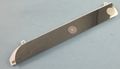
Switch board HSW-001 (top view)
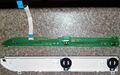
Switch board HSW-001 (PCB with ribbon cable, top view)

Switch board HSW-001, 1-881-946-11. Unknown manufacturer

Switch board HSW-001 (PCB top view)
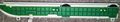
Switch board HSW-001 (PCB bottom view), 1-881-946-21. Produced by Foxconn
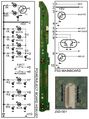
Switch board HSW-001 (JSD-001) schematic
Switch board HSW-001 (Contour LEDs subcircuit, unpopulated components)
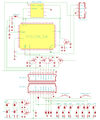
PS3 Power control and switches schematic for CECH-25xx series
Motherboards JTP-001 or JSD-001, SYSCON SW-x series, Switch board HSW-001, and 4 pins PSU connector (CN101) for PSU models APS-270 or EADP-200DB
.jpg)
.jpg)
_schematic.jpg)

Pinout
| Pin | Name | Connected to | Description | |
|---|---|---|---|---|
| On Motherboard | On Switch board | |||
| 1 | SW_PWM ? | Syscon SW2-30x, pin 12 | 4x CONTOUR LEDs, transistor base pin | The transistor is located in the switch board and drives 2 LEDs with currentlimitor resistors of 3K Ω (red led at left-top) and 820 Ω (blue led at left-bottom) The circuit has unpopulated pads to add another transistor and another 2 LEDs for a total of 4 LEDs driven by a misterious syscon pin |
| 2 | +5V_EVER | Power Supply Connector (CN101), pin 1 | VCC | 5V Standby line from power supply connector CN101, the pin named 5V_EVER on motherboard and 5VSB on power supply |
| 3 | ? | Syscon SW2-30x, pin 11 | 2x White leds - | Inner LEDs for EJECT button backlight, with a currentlimitor resistor of 910 Ω |
| 2x White leds - | Inner LEDs for POWER button backlight, with a currentlimitor resistor of 1K Ω | |||
| 4 | GND | GND | GND | Ground |
| 5 | EJECT_SW | Syscon SW2-30x, pin 111 | Eject switch |
Sink to ground to activate |
| 6 | POW_SW | Syscon SW2-30x, pin 110 | Power switch |
Sink to ground to activate |
| 7 | POW_LED | Syscon SW2-30x, pin 5 | Green led - | Connects to left-bottom corner pin (green gnd) of dual red/green LED located next to the power switch, with a currentlimitor resistor of 1K Ω |
| 8 | STBY_LED | Syscon SW2-30x, pin 6 | Red led - | Connects to left-top corner pin (red gnd) of dual red/green LED located next to the power switch, with a currentlimitor resistor of 1K2 Ω |
| 9 | BD_LED | BluRay controller CXD5131R-1, pin 36 (on SUR-001/JSD-001) or BluRay controller R8J32830FPV1, pin ?? (on JTP-001) |
Blue led - | Connects to blue LED located next to the eject switch, with a currentlimitor resistor of 560 Ω |
| 10 | GND | GND | GND | Ground |
How it works
All LED's on the switch board are turned on/off either by syscon or by the BD drive by using an intermediary transistor that drives the LED ground pin (and the other pin of the LED's is connected permanently to the 5 volts standby line present in the switch board at all times). All LED's have its own resistor with a different value to control the current (thus light intensity) and one or more diodes to protect the circuit
When Power and/or Eject switches are pressed the correlating syscon pins are pulled down (grounded)
- Contour LED's
- Are separated from the rest of the board by a transistor, the transistor is activated by a volts signal from PIN1 of the connector, but the motherboard doesnt send this signal, see Discussion
- There are several ways to re-enable the contour LED's. And there are solder points without components to duplicate this subcircuit to add another 2 LEDs more for a total of 4
| ||||||||||||||||||||||||||||||||||||||||||||||||||||||||||||||||||||||||||||||||||||||||||||||||||||||||||||||||||||||||||||||||||||
