Service Connectors: Difference between revisions
Jump to navigation
Jump to search
m (→2nd Generation) |
m (→1st Generation) |
||
| Line 9: | Line 9: | ||
{| class="wikitable" | {| class="wikitable" | ||
! Used on !! Type of Connector | ! Used on !! Type of Connector | ||
|- bgcolor="#eeeeee" | |||
| {{DEH-H1001-D}} || ZIF Connector <!-- Kyocera 046240030003800+ --> | |||
|- bgcolor="#eeeeee" | |||
| {{DEH-H1000A-E}} || Plain socket | |||
|- bgcolor="#eeeeee" | |||
| {{DECHA}} || ? | |||
|- bgcolor="#eeeeee" | |||
| {{DECHA00}} || ? | |||
|- | |- | ||
| | | {{CECHA}} || Plain socket | ||
|- | |- | ||
| | | {{CECHB}} || Plain socket | ||
|- | |- | ||
| | | {{CECHC}} || Plain socket | ||
|- | |- | ||
| | | {{CECHE}} || Plain socket | ||
|- | |- | ||
|} | |} | ||
===CN4009=== | ===CN4009=== | ||
<div style="float:right">[[File:PS3 PinJIG Connector 1st Generation COK-002.jpg|100px|thumb|left|First Generation Connector as seen on COK-002]]</div> | <div style="float:right">[[File:PS3 PinJIG Connector 1st Generation COK-002.jpg|100px|thumb|left|First Generation Connector as seen on [[COK-00x#COK-002|COK-002]]]]</div> | ||
<div style="float:right">[[File:PS3 PinJIG Connector 1st Generation COOKIE-13.jpg|100px|thumb|left|First Generation Connector as seen on COOKIE-13]]</div> | <div style="float:right">[[File:PS3 PinJIG Connector 1st Generation COOKIE-13.jpg|100px|thumb|left|First Generation Connector as seen on [[COOKIE-13]]]]</div> | ||
{| class="wikitable" | {| class="wikitable" | ||
! Pin !! Name !! Connected to !! Function !! Group | ! Pin !! Name !! Connected to !! Function !! Group | ||
Revision as of 07:32, 20 May 2013

JTAG/UART/SPI/Diagnostic I/O used in Sony repair centers if a PS3 couldn't be fixed by software.
Note: EBUS and NOR Interface Testpoints are the storage related service points used with pinJIG/pogopin infactory
Service Connectors
1st Generation
| Used on | Type of Connector |
|---|---|
| DEH-H1001-D (COOKIE-13) 0x1 | ZIF Connector |
| DEH-H1000A-E (COK-001 (Prototype)) 0x1 | Plain socket |
| DECHA (COK-001) 0x1 | ? |
| DECHA00A/J (COK-001) 0x1 | ? |
| CECHA (COK-001) 0x1 | Plain socket |
| CECHB (COK-001) 0x2 | Plain socket |
| CECHC (COK-002) 0x3 | Plain socket |
| CECHE (COK-002/COK-002W) 0x4 | Plain socket |
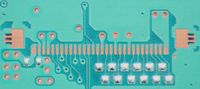
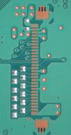
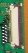
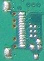
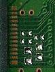
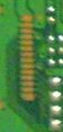
CN4009

First Generation Connector as seen on COK-002

First Generation Connector as seen on COOKIE-13
| Pin | Name | Connected to | Function | Group |
|---|---|---|---|---|
| 1 | +5V_EVER | DC-DC Regulator | +5V line | - |
| 2 | TRST | Syscon | Test Reset (nTRST) | Syscon JTAG |
| 3 | TDI | Syscon | Test Data In | |
| 4 | RTCK | Syscon | Return Test Clock | |
| 5 | TCK | Syscon | Test Clock | |
| 6 | TDO | Syscon | Test Data Out | |
| 7 | TMS | Syscon | Test Mode Select | |
| 8 | SC_RESET | Syscon | System Reset (nSRST) | |
| 9 | GND | DC-DC Regulator | Ground line | - |
| 10 | RxD | Syscon | Serial Receive | Syscon UART |
| 11 | TxD | Syscon | Serial Transmit | |
| 12 | GND | DC-DC Regulator | Ground line | - |
| 13 | Diag Mode | Syscon | Diagnose Mode | Syscon Modes |
| 14 | Backup Mode | Syscon | Backup Mode | |
| 15 | +3.3V_EVER | DC-DC Regulator | +3.3V line | - |
| 16 | NC | - | - | |
| 17 | RMC | Syscon | Remote Control | Syscon Modes |
| 18 | SB_TxD | South Bridge | Serial Transmit | South Bridge UART |
| 19 | SB_RxD | South Bridge | Serial Receive | |
| 20 | SW_4_A | (W)LAN | Power Switch | LAN & WLAN |
| 21 | BE_TRG_OUT | Cell | Trigger Out | Component Tests |
| 22 | RSX_TAB_OUT | RSX | Trigger Out | |
| 23 | SB_TRG_OUT | South Bridge | Trigger Out | |
| 24 | BE_CHKSTP_OUT | CELL | Checkstop Out | |
| 25 | RSX_CHKSTP_OUT | RSX | Checkstop Out | |
| 26 | SB_CHKSTP_OUT | South Bridge | Checkstop Out | |
| 27 | +1.2V_MC_VDDIO | DC-DC Regulator | +1.2V line | - |
| 28 | +1.5V_RSX_VDDIO | DC-DC Regulator | +1.5V line | |
| 29 | GND | DC-DC Regulator | Ground line | |
| 30 | +5V_EVER | DC-DC Regulator | +5V line |
2nd Generation
| Used on | Type of Connector |
|---|---|
| CECHG (SEM-001) 0x5 | Plain socket |
| CECHH (DIA-001) 0x6 | Plain socket |
| CECHJ (DIA-002) 0x7 | Plain socket |
| CECHK (DIA-002) 0x7 | Plain socket |
| DECHJ00A/J (DIA-002) 0x7 | ? |
| DECR-1400A/J (DEB-001) 0x09 | Plain socket |

CN4003
| Pin | Name | Connected to | Function | Group |
|---|---|---|---|---|
| 10 | SC_TXD | SysCon | Serial Transmit | Syscon UART |
| 9 | SC_RXD | SysCon | Serial Receive | |
| 8 | RMC | SysCon | Remote Control | Syscon Modes |
| 7 | Diag Mode | SysCon | Diagnose Mode | |
| 6 | Backup Mode | SysCon | Backup Mode | |
| 5 | SB_SIO0_RXD_M | South Bridge | Serial Receive | South Bridge UART |
| 4 | SB_SIO0_TXD_M | South Bridge | Serial Transmit | |
| 3 | SW_4_B | USB | Power Switch | USB |
| 2 | +5V_EVER | DC-DC Regulator | +5V line | - |
| 1 | GND | DC-DC Regulator | Ground line |
CN4004
| Pin | Name | Connected to | Function | Group |
|---|---|---|---|---|
| 10 | TRST | SysCon | Test Reset (nTRST) | Syscon JTAG |
| 9 | TDI | SysCon | Test Data In | |
| 8 | RTCK | SysCon | Return Test Clock | |
| 7 | TCK | SysCon | Test Clock | |
| 6 | TDO | SysCon | Test Data Out | |
| 5 | TMS | SysCon | Test Mode Select | |
| 4 | SC_RESET | SysCon | System Reset (nSRST) | |
| 3 | +3.3V_EVER | DC-DC Regulator | +3.3V line | - |
| 2 | GND | DC-DC Regulator | Ground line | |
| 1 | GND | DC-DC Regulator | Ground line |
3rd Generation
| Used on | Type of Connector |
|---|---|
| CECHL (VER-001) 0x8 | Plain socket |
| CECHM (VER-001) 0x8 | Plain socket |
| CECHP (VER-001) 0x8 | Plain socket |
| Template:CECHQ | Plain socket |
| ARC GECR-1500 (VER-001) 0x8 | Plain socket |
| CECH-20xx (DYN-001) 0x09 | Plain socket |
| CECH-21xx (SUR-001) 0xA | Plain socket |
| . (SURTEES-03) 0xA | Unknown Connector |
| CECH-25xx (JSD-001/JTP-001) 0xB | Plain socket |
| CECH-30xx (KTE-001) 0xC | Plain socket |
| CECH-40xx (MPX-001/MSX-001) 0xD | Plain socket |
Third Generation Service Connector as seen on VER-001

Third Service Generation Connector as seen on DYN-001

Third Generation Service Connector as seen on DYN-001
Third Generation Service Connector as seen on JSD-001
Third Generation Service Connector as seen on MPX-001

Third Service Generation Connector as seen on SURTEES-03


CN????
| Pin | Name | Connected to | Function | Group |
|---|---|---|---|---|
| 14 | ? | ? | ? | |
| 13 | ? | ? | ? | |
| 12 | ? | ? | ? | |
| 11 | ? | ? | ? | |
| 9 | ? | ? | ? | |
| 8 | ? | ? | ? | |
| 7 | ? | ? | ? | |
| 6 | ? | ? | ? | |
| 5 | ? | ? | ? | |
| 4 | ? | ? | ? | |
| 3 | ? | ? | ? | |
| 2 | ? | ? | ? | |
| 1 | ? | ? | ? |