APS-227: Difference between revisions
Jump to navigation
Jump to search
No edit summary |
m (Replaced pinout table by a template) |
||
| Line 4: | Line 4: | ||
1-474-046-11 | 1-474-046-11 | ||
=== Pinout === | === Pinout === | ||
{ | {{PS3 PSU Control connector 5 pins}} | ||
=== Gallery === | === Gallery === | ||
Latest revision as of 02:36, 27 March 2021
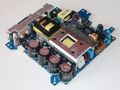
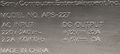
APS-227[edit | edit source]

1-474-046-11
Pinout[edit | edit source]
| Pin # | Name | Description |
|---|---|---|
| 1 | ACDC_STBY | Switch main output |
| 2 | GND | Ground |
| 3 | GND | Ground |
| 4 | 5VSB | Standby voltage |
| 5 | 5VSB | Standby voltage |
Gallery[edit | edit source]
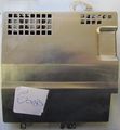
APS-227 (top view)
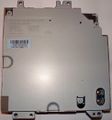
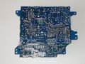
APS-227 (bottom view)
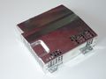
APS-227 (top view, perspective 1)
APS-227 M (top view, perspective 1)
APS-227 M (top view, perspective 2)
File:APS-227 M (bottom view)
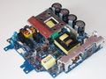
APS-227 (Power)
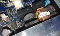
APS-227 (damaged)

.jpg)
.jpg)
.jpg)
.jpg)


Potmeters[edit | edit source]
| Label | Partno. | Description |
|---|---|---|
PFC +B ADJ |
RV301 | PowerFactorCorrection +B Adjust |
OCP ADJ |
RV302 | OverCurrentProtection Adjust |
Fmin ADJ |
RV303 | Minimum Switching Frequency Adjust |
PFC Freq ADJ |
RV304 | PowerFactorCorrection Frequency Adjust |
| ||||||||||||||||||||||||||||||||||||||||||||||||||||||||||||||||||||||||||||||||||||||||||||||||||||||||||||||||||||||||||||||||||||
