Switch boards: Difference between revisions
(cleanup/updated some sections) |
|||
| (123 intermediate revisions by 7 users not shown) | |||
| Line 1: | Line 1: | ||
= Description = | |||
The [[Switch boards|Switch board]] is a daughterboard where are located the input switches, and some leds for outputs and fireworks | |||
*'''Switch board components''' | |||
**'''Switches''': Power and Eject buttons | |||
**'''Green and Red leds''', all switch board models have them, are needed to show the standby/poweron modes and the infamous YLOD | |||
**'''Eject led''', this is the only led not controlled by syscon, the line goes to the bluray controller, so is the bluray controller who decides when is lighted on | |||
**'''White backlight leds''', this was added for PS3 slim models with the new case design and the new pressure buttons (not touch sensitive) | |||
**'''Unknown subcircuit leds''', this seems some kind of experiment that escaped the prototyping table and entered retail production, for some reason exists in some retail PS3 but seems deactivated and partially unpopulated | |||
**'''IC''', there are a couple of "chips" only in the first model of the switch board, probably related with the touch sensitive feature and maybe others | |||
*'''Switch board circuit overview''' (based on how [[HSW-001]] works, this could be different for other switch board models) | |||
**When Power or Eject switches are pressed the correlating syscon pins are pulled down (grounded) | |||
**All LED's have its own resistor with a different value to control the current (thus light intensity) and one or more diodes to protect the circuit | |||
**The LED's on the switch board are turned on either by syscon (all them except one) or by the BD drive controller (only the eject blue led) by using an intermediary transistor | |||
**That transistors connects the LED ground pin to ground when the signal to turn them on is sent by syscon or by the BD drive controller (the other pin of the LED is connected permanently to the 5 volts standby line) | |||
== | = Comparison of functionality = | ||
{| class="wikitable" style="line-height:120%" | |||
|+PS3 retail switch boards | |||
! colspan="2" | PS3 !! colspan="3" | Switch board !! colspan="2" | Switches || colspan="4" | Leds | |||
{| class="wikitable | |||
|+ | |||
! | |||
| | |||
|- | |- | ||
| | ! [[SKU_Models|PS3 Model]] !! [[Motherboard_Revisions|Motherboard]] !! Model !! Part number !! Connector !! Power !! Eject !! Standby/PowerOn/<abbr title="Yellow color is made by lighting red + green leds together">YLOD</abbr> !! Eject !! Switches Backlight !! Board Contour Backlight | ||
|- | |- | ||
| 2 || style="color: | | [[CECHAxx]]<BR/>[[CECHBxx]] | ||
| [[COK-001]] | |||
| rowspan="2" | [[CSW-001]] || rowspan="2" | 1-871-871-21 || rowspan="2" | 10 pins || rowspan="2" | Touch sensitive || rowspan="2" | Touch sensitive | |||
| rowspan="2" | 1x <span style="color:#ffffff; background:#ff0000; outline:1px solid #444444;"> red </span> (2 pins)<BR/>1x <span style="color:#ffffff; background:#00ff00; outline:1px solid #444444;"> green </span> (2 pins) || rowspan="2" | 1x <span style="color:#ffffff; background:#aaaaff; outline:1px solid #444444;"> blue </span> || rowspan="2" style="background:lightgrey; text-align:center;" | N/A || rowspan="2" style="background:lightgrey; text-align:center;" | N/A | |||
|- | |- | ||
| | | [[CECHCxx]]<BR/>[[CECHExx]] | ||
| [[COK-002]] | |||
|- | |- | ||
| 4 || style="color: | | [[CECHGxx]] | ||
| [[SEM-001]] | |||
| colspan="3" rowspan="4" style="background:lightgrey; text-align:center;" | Integrated on motherboard || rowspan="4" | Touch sensitive || rowspan="4" | Touch sensitive | |||
| rowspan="4" | 1x <span style="color:#ffffff; background:#ff0000; outline:1px solid #444444;"> red </span> (2 pins) ?<BR/>1x <span style="color:#ffffff; background:#00ff00; outline:1px solid #444444;"> green </span> (2 pins) ? || rowspan="4" | 1x <span style="color:#ffffff; background:#aaaaff; outline:1px solid #444444;"> blue </span> || rowspan="4" style="background:lightgrey; text-align:center;" | N/A || rowspan="4" style="background:lightgrey; text-align:center;" | N/A | |||
|- | |||
| [[CECHHxx]] | |||
| [[DIA-001]] | |||
|- | |||
| [[CECHJxx]]<BR/>[[CECHKxx]] | |||
| [[DIA-002]] | |||
|- | |||
| [[CECHLxx]]<BR/>[[CECHMxx]]<BR/>[[CECHPxx]]<BR/>[[CECHQxx]] | |||
| [[VER-001]] | |||
|- | |||
| style="padding:0px" colspan="11" | | |||
|- | |- | ||
| | | [[CECH-20xx]] | ||
| [[DYN-001]] | |||
| [[DSW-001]] || 1-880-056-11 || 10 pins || Pressure || Pressure | |||
| 1x dual <span style="color:#ffffff; background:#ff0000; outline:1px solid #444444;"> red </span> / <span style="color:#ffffff; background:#00ff00; outline:1px solid #444444;"> green </span> (4 pins) || 1x <span style="color:#ffffff; background:#aaaaff; outline:1px solid #444444;"> blue </span> || 2x <span style="color:#000000; background:#ffffff; outline:1px solid #444444;"> white </span> (power)<BR/>2x <span style="color:#000000; background:#ffffff; outline:1px solid #444444;"> white </span> (eject) || 1x <span style="color:#ffffff; background:#ff0000; outline:1px solid #444444;"> red </span> (left-top). 1x <span style="color:#ffffff; background:#aaaaff; outline:1px solid #444444;"> blue </span> (right-top)<BR/>1x <span style="color:#ffffff; background:#aaaaff; outline:1px solid #444444;"> blue </span> (left-bottom). 1x <span style="color:#000000; background:lightgrey; outline:1px solid #444444;"> N/A </span> (right-bottom) | |||
|- | |- | ||
| | | [[CECH-21xx]] | ||
| [[SUR-001]] | |||
| rowspan="2" | [[HSW-001]] || rowspan="2" | 1-881-946-11/21 || rowspan="2" | 10 pins || rowspan="2" | Pressure || rowspan="2" | Pressure | |||
| rowspan="2" | 1x dual <span style="color:#ffffff; background:#ff0000; outline:1px solid #444444;"> red </span> / <span style="color:#ffffff; background:#00ff00; outline:1px solid #444444;"> green </span> (4 pins) || rowspan="2" | 1x <span style="color:#ffffff; background:#aaaaff; outline:1px solid #444444;"> blue </span> || rowspan="2" | 2x <span style="color:#000000; background:#ffffff; outline:1px solid #444444;"> white </span> (power)<BR/>2x <span style="color:#000000; background:#ffffff; outline:1px solid #444444;"> white </span> (eject) || rowspan="2" | 1x <span style="color:#ffffff; background:#ff0000; outline:1px solid #444444;"> red </span> (left-top). 1x <span style="color:#000000; background:lightgrey; outline:1px solid #444444;"> N/A </span> (right-top)<BR/>1x <span style="color:#ffffff; background:#aaaaff; outline:1px solid #444444;"> blue </span> (left-bottom). 1x <span style="color:#000000; background:lightgrey; outline:1px solid #444444;"> N/A </span> (right-bottom) | |||
|- | |- | ||
| | | [[CECH-25xx]] | ||
| [[JTP-001]]<BR/>[[JSD-001]] | |||
|- | |- | ||
| | | [[CECH-30xx]] | ||
| [[KTE-001]] | |||
| [[KSW-001]] || 1-884-751-31 || 6 pins || Pressure || Pressure | |||
| 1x dual <span style="color:#ffffff; background:#ff0000; outline:1px solid #444444;"> red </span> / <span style="color:#ffffff; background:#00ff00; outline:1px solid #444444;"> green </span> (4 pins) || style="background:lightgrey; text-align:center;" | N/A || style="background:lightgrey; text-align:center;" | N/A || style="background:lightgrey; text-align:center;" | N/A | |||
|- | |||
| style="padding:0px" colspan="11" | | |||
|- | |- | ||
| | | rowspan="3" | SuperSlim | ||
| [[MSX-001]]<BR/>[[MPX-001]]<BR/>[[NPX-001]] ? | |||
| [[MSW-001]] || 1-886-929-11/21/31 || 6 pins || Pressure || style="background:lightgrey; text-align:center;" | N/A | |||
| 1x dual <span style="color:#ffffff; background:#ff0000; outline:1px solid #444444;"> red </span> / <span style="color:#ffffff; background:#00ff00; outline:1px solid #444444;"> green </span> (4 pins) || style="background:lightgrey; text-align:center;" | N/A || style="background:lightgrey; text-align:center;" | N/A || style="background:lightgrey; text-align:center;" | N/A | |||
|- | |- | ||
| | | [[PPX-001]]<BR/>[[PQX-001]] | ||
| [[PSW-001]] || 1-888-628-21 || 6 pins ? || Pressure || style="background:lightgrey; text-align:center;" | N/A | |||
| 1x dual <span style="color:#ffffff; background:#ff0000; outline:1px solid #444444;"> red </span> / <span style="color:#ffffff; background:#00ff00; outline:1px solid #444444;"> green </span> (4 pins) || style="background:lightgrey; text-align:center;" | N/A || style="background:lightgrey; text-align:center;" | N/A || style="background:lightgrey; text-align:center;" | N/A | |||
|- | |- | ||
| [[RTX-001]]<BR/>[[REX-001]] | |||
| [[RSW-001]] || 1-893-506-11/31 || 6 pins ? || Pressure || style="background:lightgrey; text-align:center;" | N/A | |||
| 1x dual <span style="color:#ffffff; background:#ff0000; outline:1px solid #444444;"> red </span> / <span style="color:#ffffff; background:#00ff00; outline:1px solid #444444;"> green </span> (4 pins) || style="background:lightgrey; text-align:center;" | N/A || style="background:lightgrey; text-align:center;" | N/A || style="background:lightgrey; text-align:center;" | N/A | |||
|} | |} | ||
*Notes | *Notes | ||
** | **The names of the first Switch Board models are composed by the first letter of the first PS3 motherboard that used the switch board + the suffix '''SW''' (acronym of '''SW'''itch). E.g: [[COK-001|'''C'''OK-001]]=[[CSW-001|'''C'''SW-001]], [[DYN-001|'''D'''YN-001]]=[[DSW-001|'''D'''SW-001]] | ||
**Since [[CECH-21xx]]/[[SUR-001]] the first character of the switch board name indicates the [[Chassis_ID|Chasis Type]], included in the [[Platform ID]]. E.g: [[SUR-001]] = Cok'''H'''11 so his switch board was named [[HSW-001|'''H'''SW-001]] | |||
** | |||
= | = Flex Ribbon cables = | ||
<gallery> | <gallery> | ||
File:Power Eject | File:Power Eject Flex Ribbon Cable (PS3 1000 series, top view).jpg|Switch board Flex Ribbon Cable (PS3 1000 series, top view) | ||
File:Power Eject | File:Power Eject Flex Ribbon Cable (PS3 1000 series, bottom view).jpg|Switch board Flex Ribbon Cable (PS3 1000 series, bottom view) | ||
File:Power Eject | File:Power Eject Flex Ribbon Cable (PS3 2000 series, top view).jpg|Switch board Flex Ribbon Cable (PS3 2000 series, top view) | ||
File:Power Eject | File:Power Eject Flex Ribbon Cable (PS3 3000 series, top view).jpg|Switch board Flex Ribbon Cable (PS3 3000 series, top view) | ||
File:Power Eject Flex Ribbon Cable (PS3 3000 series, bottom view).jpg|Switch board Flex Ribbon Cable (PS3 3000 series, bottom view) | |||
</gallery> | </gallery> | ||
== | = Switch boards Pinout = | ||
== CSW-001 == | |||
<div style="float:right">[[File:Power Eject board CSW-001 (PCB top view).jpg|500px|thumb|left|Switch board CSW-001 (PCB top view)]]</div> | |||
*[[CSW-001]] is a [[Switch boards|switch board]] compatible with PS3 models: | |||
**[[CECHAxx]], [[CECHBxx]] with motherboard [[COK-001]] | |||
**[[CECHCxx]], [[CECHExx]] with motherboard [[COK-002]] | |||
{{CSW-001 pinout}} | |||
== DSW-001 == | |||
<div style="float:right">[[File:Power Eject board DSW-001 (PCB top view).jpg|500px|thumb|left|Switch board DSW-001 (PCB top view)]]</div> | |||
*[[DSW-001]] is a [[Switch boards|switch board]] compatible with PS3 models: | |||
**[[CECH-20xx]] with [[DYN-001]] motherboard | |||
{{DSW-001 pinout}} | |||
== HSW-001 == | |||
<div style="float:right">[[File:Power Eject board HSW-001 (PCB top view).jpg|500px|thumb|left|Switch board HSW-001 (PCB top view)]]</div> | |||
*[[HSW-001]] is a [[Switch boards|switch board]] compatible with PS3 models: | |||
**[[CECH-21xx]] with [[SUR-001]] motherboard | |||
**[[CECH-25xx]] with [[JTP-001]] or [[JSD-001]] motherboards | |||
{{clear}} | |||
{{HSW-001 pinout}} | |||
< | == KSW-001 == | ||
File:Power Eject board | <div style="float:right">[[File:Power Eject board KSW-001 (PCB top view).jpg|600px|thumb|left|Switch board KSW-001 (PCB top view)]]</div> | ||
*[[KSW-001]] is a [[Switch boards|switch board]] compatible with PS3 models: | |||
**[[CECH-30xx]] with [[KTE-001]] motherboard | |||
{{KSW-001 pinout}} | |||
= | == MSW-001 == | ||
<div style="float:right">[[File:Power Eject board MSW-001 (PCB top view).jpg|700px|thumb|left|Switch board MSW-001 (PCB top view)]]</div> | |||
< | *[[MSW-001]] is a [[Switch boards|switch board]] compatible with PS3 models: | ||
File:Power Eject | **[[MSX-001]], [[MPX-001]] | ||
{{MSW-001 pinout}} | |||
== PSW-001 == | |||
*[[PSW-001]] is a [[Switch boards|switch board]] compatible with PS3 models: | |||
**[[PPX-001]], [[PQX-001]] | |||
PSW-001 pinout... is the same than MSW-001 ? | |||
== RSW-001 == | |||
*[[RSW-001]] is a [[Switch boards|switch board]] compatible with PS3 models: | |||
**[[RTX-001]], [[REX-001]] | |||
RSW-001 pinout... is the same than MSW-001 ? | |||
= Modding = | = Modding = | ||
== Contour backlight in | == Contour backlight in PS3 2000 Series boards == | ||
PS3 2000 series ([[CECH-20xx]], [[CECH-21xx]] | <div style="float:right">[[File:Power Eject board PS3 2000 series (light rays schematic in contour leds).jpg|500px|thumb|left|Switch board PS3 2000 series<BR />Light rays schematic in contour leds]]</div> | ||
PS3 2000 series [[CECH-20xx]] (with Switch board [[DSW-001]]), [[CECH-21xx]] and [[CECH-25xx]] (with Switch board [[HSW-001]]) has been designed to have a lighted line all around the top edge of the Switch board | |||
The plastic plate uses a "light reactive" material along the edge and in a squared hole in the corner allows the light to "transpass" it | The plastic plate uses a "light reactive" material along the edge and in a squared hole in the corner allows the light to "transpass" it | ||
| Line 132: | Line 147: | ||
The ligth rays "bounces" inside this material, and the first bouncing surface over the squared hole is a plane at 45 degrees angle. This first bounce aligns the light rays in paralell to the board, the next bounces happens all along the curved surface in horizontal | The ligth rays "bounces" inside this material, and the first bouncing surface over the squared hole is a plane at 45 degrees angle. This first bounce aligns the light rays in paralell to the board, the next bounces happens all along the curved surface in horizontal | ||
The reflection of this surfaces can be increased a bit with chrome stickers (or alluminium tape). The case has a plane border of 3,5mm x 17, | The reflection of this surfaces can be increased a bit with chrome stickers (or alluminium tape). The case has a plane border of 3,5mm x 17,7cm perfect to stick in it, this way the glue layer of the sticker is at the other side, but the case doesnt have the 45 degrees surface (it has a weird hole instead), you can use other colors for the sticker/s because the color is partially visible from outside (preferably lighter colors or one that matches your led/s color to enhance it) | ||
For more detailed info about this boards see: [[DSW-001]] and [[HSW-001]] pages | |||
{| class="wikitable" | |||
|- | |||
| {{#ev:youtube|leapBkrm5tk}} || {{#ev:youtube|FUk1q4af7TE}} | |||
|- | |||
| PS3 [[CECH-20xx]] Switch board [[DSW-001]]. Tests || PS3 [[CECH-25xx]] Switch board [[HSW-001]]. Enabled subcircuit with 2 leds (blue + red) | |||
|} | |||
[[Category: | {{Components}}<noinclude>[[Category:Main]]</noinclude> | ||
Latest revision as of 19:27, 5 December 2021
Description[edit | edit source]
The Switch board is a daughterboard where are located the input switches, and some leds for outputs and fireworks
- Switch board components
- Switches: Power and Eject buttons
- Green and Red leds, all switch board models have them, are needed to show the standby/poweron modes and the infamous YLOD
- Eject led, this is the only led not controlled by syscon, the line goes to the bluray controller, so is the bluray controller who decides when is lighted on
- White backlight leds, this was added for PS3 slim models with the new case design and the new pressure buttons (not touch sensitive)
- Unknown subcircuit leds, this seems some kind of experiment that escaped the prototyping table and entered retail production, for some reason exists in some retail PS3 but seems deactivated and partially unpopulated
- IC, there are a couple of "chips" only in the first model of the switch board, probably related with the touch sensitive feature and maybe others
- Switch board circuit overview (based on how HSW-001 works, this could be different for other switch board models)
- When Power or Eject switches are pressed the correlating syscon pins are pulled down (grounded)
- All LED's have its own resistor with a different value to control the current (thus light intensity) and one or more diodes to protect the circuit
- The LED's on the switch board are turned on either by syscon (all them except one) or by the BD drive controller (only the eject blue led) by using an intermediary transistor
- That transistors connects the LED ground pin to ground when the signal to turn them on is sent by syscon or by the BD drive controller (the other pin of the LED is connected permanently to the 5 volts standby line)
Comparison of functionality[edit | edit source]
| PS3 | Switch board | Switches | Leds | |||||||
|---|---|---|---|---|---|---|---|---|---|---|
| PS3 Model | Motherboard | Model | Part number | Connector | Power | Eject | Standby/PowerOn/YLOD | Eject | Switches Backlight | Board Contour Backlight |
| CECHAxx CECHBxx |
COK-001 | CSW-001 | 1-871-871-21 | 10 pins | Touch sensitive | Touch sensitive | 1x red (2 pins) 1x green (2 pins) |
1x blue | N/A | N/A |
| CECHCxx CECHExx |
COK-002 | |||||||||
| CECHGxx | SEM-001 | Integrated on motherboard | Touch sensitive | Touch sensitive | 1x red (2 pins) ? 1x green (2 pins) ? |
1x blue | N/A | N/A | ||
| CECHHxx | DIA-001 | |||||||||
| CECHJxx CECHKxx |
DIA-002 | |||||||||
| CECHLxx CECHMxx CECHPxx CECHQxx |
VER-001 | |||||||||
| CECH-20xx | DYN-001 | DSW-001 | 1-880-056-11 | 10 pins | Pressure | Pressure | 1x dual red / green (4 pins) | 1x blue | 2x white (power) 2x white (eject) |
1x red (left-top). 1x blue (right-top) 1x blue (left-bottom). 1x N/A (right-bottom) |
| CECH-21xx | SUR-001 | HSW-001 | 1-881-946-11/21 | 10 pins | Pressure | Pressure | 1x dual red / green (4 pins) | 1x blue | 2x white (power) 2x white (eject) |
1x red (left-top). 1x N/A (right-top) 1x blue (left-bottom). 1x N/A (right-bottom) |
| CECH-25xx | JTP-001 JSD-001 | |||||||||
| CECH-30xx | KTE-001 | KSW-001 | 1-884-751-31 | 6 pins | Pressure | Pressure | 1x dual red / green (4 pins) | N/A | N/A | N/A |
| SuperSlim | MSX-001 MPX-001 NPX-001 ? |
MSW-001 | 1-886-929-11/21/31 | 6 pins | Pressure | N/A | 1x dual red / green (4 pins) | N/A | N/A | N/A |
| PPX-001 PQX-001 |
PSW-001 | 1-888-628-21 | 6 pins ? | Pressure | N/A | 1x dual red / green (4 pins) | N/A | N/A | N/A | |
| RTX-001 REX-001 |
RSW-001 | 1-893-506-11/31 | 6 pins ? | Pressure | N/A | 1x dual red / green (4 pins) | N/A | N/A | N/A | |
- Notes
- The names of the first Switch Board models are composed by the first letter of the first PS3 motherboard that used the switch board + the suffix SW (acronym of SWitch). E.g: COK-001=CSW-001, DYN-001=DSW-001
- Since CECH-21xx/SUR-001 the first character of the switch board name indicates the Chasis Type, included in the Platform ID. E.g: SUR-001 = CokH11 so his switch board was named HSW-001
Flex Ribbon cables[edit | edit source]
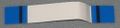
Switch board Flex Ribbon Cable (PS3 1000 series, top view)
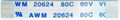
Switch board Flex Ribbon Cable (PS3 1000 series, bottom view)
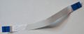
Switch board Flex Ribbon Cable (PS3 2000 series, top view)
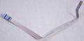
Switch board Flex Ribbon Cable (PS3 3000 series, top view)
Switch board Flex Ribbon Cable (PS3 3000 series, bottom view)
.jpg)
.jpg)
Switch boards Pinout[edit | edit source]
CSW-001[edit | edit source]
.jpg)
- CSW-001 is a switch board compatible with PS3 models:
| Pin | Name | Connected to | Description | |
|---|---|---|---|---|
| On Motherboard | On Switch board | |||
| 1 | GND | GND | GND | Ground |
| 2 | SW_PWM | Syscon pad N9 | Testpad ? | FREQ. Intended to send a PWM signal to the switch board ? |
| 3 | RMC_IN | Syscon pad R10 Service Connector (CN4009) pin 17 |
Testpad ?. NC | ReMote Control INput The IR receiver component is missing in the Switch board but existed in some PS3 prototypes that was using SIRC protocol and SERV_SIRCS |
| 4 | POW_SW | Syscon pad B12 | Power Switch |
|
| 5 | EJECT_SW | Syscon pad A12 | Eject Switch |
|
| 6 | POW_LED | Syscon pad M7 | Green led | |
| 7 | STBY_LED | Syscon pad N7 | Red led | |
| 8 | BD_LED | BluRay connector (CN3221) pin 50 | Blue led | |
| 9 | GND | GND | GND | Ground |
| 10 | +5V_EVER | Power Supply connector (CN6005) pins 4 and 5 | VCC | 5V Standby |
DSW-001[edit | edit source]
.jpg)
- DSW-001 is a switch board compatible with PS3 models:
| Pin | Name | Connected to | Description | |
|---|---|---|---|---|
| On Motherboard | On Switch board | |||
| 1 | RMC_IN ? | Syscon SW2-30x, pin 13 | Testpad | Only This line have a Testpad @ switchboard, seems that it is a service pin. Also connected to a pin of a Service Connectors ? |
| 2 | SW_PWM ? | Syscon SW2-30x, pin 12 | 4x CONTOUR LEDs | Permanently inactive by default. On Switch board is connected to a transistor driving 3 LEDs: TWO BLUE AND ONE RED. |
| 3 | ? | Syscon SW2-30x, pin 11 | 2x White leds - | Inner LEDs for EJECT button backlight |
| 2x White leds - | Inner LEDs for POWER button backlight | |||
| 4 | POW_SW | Syscon SW2-30x, pin 110 | Power switch |
Sink to ground to activate. |
| 5 | EJECT_SW | Syscon SW2-30x, pin 111 | Eject switch |
Sink to ground to activate. |
| 6 | POW_LED | Syscon SW2-30x, pin 5 | Green led | Connects to bottom-left corner pin (green gnd) of dual red/green LED over power switch. |
| 7 | STBY_LED | Syscon SW2-30x, pin 6 | Red led | Connects to top-left corner pin (red gnd) of dual red/green LED over power switch. |
| 8 | BD_LED | BluRay Connector, pin 13 | Blue led | Connects to blue LED over eject switch. |
| 9 | GND | GND | GND | Ground |
| 10 | +5V_EVER | Power Supply Connector (CN101), pin 1 | VCC | 5V Standby |
- above top panel view port behind pcb. resistors was not tested.
HSW-001[edit | edit source]
.jpg)
- HSW-001 is a switch board compatible with PS3 models:
| Pin | Name | Connected to | Description | |
|---|---|---|---|---|
| On Motherboard | On Switch board | |||
| 1 | SW_PWM ? | Syscon SW2-30x, pin 12 | 4x CONTOUR LEDs, transistor base pin | The transistor is located in the switch board and drives 2 LEDs with currentlimitor resistors of 3K Ω (red led at left-top) and 820 Ω (blue led at left-bottom) The circuit has unpopulated pads to add another transistor and another 2 LEDs for a total of 4 LEDs driven by a misterious syscon pin |
| 2 | +5V_EVER | Power Supply Connector (CN101), pin 1 | VCC | 5V Standby line from power supply connector CN101, the pin named 5V_EVER on motherboard and 5VSB on power supply |
| 3 | ? | Syscon SW2-30x, pin 11 | 2x White leds - | Inner LEDs for EJECT button backlight, with a currentlimitor resistor of 910 Ω |
| 2x White leds - | Inner LEDs for POWER button backlight, with a currentlimitor resistor of 1K Ω | |||
| 4 | GND | GND | GND | Ground |
| 5 | EJECT_SW | Syscon SW2-30x, pin 111 | Eject switch |
Sink to ground to activate |
| 6 | POW_SW | Syscon SW2-30x, pin 110 | Power switch |
Sink to ground to activate |
| 7 | POW_LED | Syscon SW2-30x, pin 5 | Green led - | Connects to left-bottom corner pin (green gnd) of dual red/green LED located next to the power switch, with a currentlimitor resistor of 1K Ω |
| 8 | STBY_LED | Syscon SW2-30x, pin 6 | Red led - | Connects to left-top corner pin (red gnd) of dual red/green LED located next to the power switch, with a currentlimitor resistor of 1K2 Ω |
| 9 | BD_LED | BluRay controller CXD5131R-1, pin 36 (on SUR-001/JSD-001) or BluRay controller R8J32830FPV1, pin ?? (on JTP-001) |
Blue led - | Connects to blue LED located next to the eject switch, with a currentlimitor resistor of 560 Ω |
| 10 | GND | GND | GND | Ground |
KSW-001[edit | edit source]
.jpg)
- KSW-001 is a switch board compatible with PS3 models:
| Pin | Name | Connected to | Description | |
|---|---|---|---|---|
| On Motherboard | On Switch board | |||
| 1 | EJECT_SW | Syscon SW3-30x, pin 83 ? | Eject switch |
Sink to ground to activate |
| 2 | +5V_EVER | VCC | VCC | 5V Standby |
| 3 | POW_SW | Syscon SW3-30x, pin 81 ? | Power switch |
Sink to ground to activate |
| 4 | STBY_LED | Syscon SW3-30x, pin ? | Red led | Connects to right-top corner pin (red gnd) of dual red/green LED over power switch, |
| 5 | POW_LED | Syscon SW3-30x, pin ? | Green led | Connects to top right corner pin (green gnd) of dual red/green LED over power switch, |
| 6 | GND | GND | GND | Ground |
- above top panel view port behind pcb. resistors was not tested.
MSW-001[edit | edit source]
.jpg)
- MSW-001 is a switch board compatible with PS3 models:
| Pin | Name | Connected to | Description | |
|---|---|---|---|---|
| On Motherboard | On Switch board | |||
| 1 | ? | ? | GND | |
| 2 | ? | ? | GND | |
| 3 | ? | ? | POW_SW | |
| 4 | ? | ? | POW_LED | |
| 5 | ? | ? | VCC | |
| 6 | ? | ? | STBY_LED | |
PSW-001[edit | edit source]
- PSW-001 is a switch board compatible with PS3 models:
PSW-001 pinout... is the same than MSW-001 ?
RSW-001[edit | edit source]
- RSW-001 is a switch board compatible with PS3 models:
RSW-001 pinout... is the same than MSW-001 ?
Modding[edit | edit source]
Contour backlight in PS3 2000 Series boards[edit | edit source]
.jpg)
PS3 2000 series CECH-20xx (with Switch board DSW-001), CECH-21xx and CECH-25xx (with Switch board HSW-001) has been designed to have a lighted line all around the top edge of the Switch board
The plastic plate uses a "light reactive" material along the edge and in a squared hole in the corner allows the light to "transpass" it
The ligth rays "bounces" inside this material, and the first bouncing surface over the squared hole is a plane at 45 degrees angle. This first bounce aligns the light rays in paralell to the board, the next bounces happens all along the curved surface in horizontal
The reflection of this surfaces can be increased a bit with chrome stickers (or alluminium tape). The case has a plane border of 3,5mm x 17,7cm perfect to stick in it, this way the glue layer of the sticker is at the other side, but the case doesnt have the 45 degrees surface (it has a weird hole instead), you can use other colors for the sticker/s because the color is partially visible from outside (preferably lighter colors or one that matches your led/s color to enhance it)
For more detailed info about this boards see: DSW-001 and HSW-001 pages
| PS3 CECH-20xx Switch board DSW-001. Tests | PS3 CECH-25xx Switch board HSW-001. Enabled subcircuit with 2 leds (blue + red) |
| ||||||||||||||||||||||||||||||||||||||||||||||||||||||||||||||||||||||||||||||||||||||||||||||||||||||||||||||||||||||||||||||||||||
